Built-in clutch and combined motor with same

A clutch, built-in technology, applied in the direction of clutches, magnetic drive clutches, non-mechanical drive clutches, etc., can solve problems such as unreasonable force structure, troublesome motor assembly, jamming, etc., to improve the torque transmission per unit space and avoid Clutch failure, the effect of ensuring stability

Active Publication Date: 2013-07-17
湖州荣辉进出口有限公司
View PDF7 Cites 3 Cited by
  • Summary
  • Abstract
  • Description
  • Claims
  • Application Information

AI Technical Summary

Problems solved by technology

The existing patent technology discloses a small clutch and a motor using the clutch, and electric curtains (authorized announcement number CN101871493B). Although the traditional clutch structure can provide the effect of the clutch, it is indeed progressive, but it is not practical in actual use. It is found that there are still many deficiencies in its own structure and performance, causing the existing clutches to fail to achieve the best use effect and work efficiency in practical applications. The shortcomings are described in detail as follows:
[0004] 1. In the traditional clutch, only the disc is a magnetizer, while the cam and the notch shell are all non-magnetizers. The slider can be freely in the gap between the part of the cam that does not protrude to the inner wall of the notch shell and the notch shell. Therefore, the slider cannot form a fixed trajectory during motion. It is precisely because the trajectory of the slider is unfixed and uncontrollable that the slider has a large space on the disc and can slide arbitrarily, so that the slider is embedded in the notch. The timing of the notch of the shell is also uncertain, and it is very easy to have serious problems such as abnormal clutch failure and jamming. The stability of the product clutch is poor
[0005] 2. The traditional clutch adopts the fast insertion method. Since the space of the notch is too small, the combination of the slider and the notch is completed in an instant. However, in order to achieve a better combination effect, the cam adopts a hypotenuse structure. The flatter the hypotenuse and the circle tangent, the better the embedding effect, but at the same time, the more unreasonable the force structure is, the useless radial component force is equivalent to its effective Due to the large radial force of the material, the design of the wall thickness of the notch shell is large, and in order to ensure the safety of the notch shell, it is necessary to design the shell cover to the notch shell outside the notch shell. For protection, the radial space of the product is designed to be very large, and the torque transmission per unit radial space is very small; when the angle between the hypotenuse and the circle tangent is large, the embedding effect of the slider is very poor, and even the phenomenon that it cannot be embedded appears.
[0006] 3. There is no reliable concentric design between the driving part and the driven part of the traditional clutch. There is a disc structure that must be fixed between the radial connection of the driving part and the driven part. The radial gap is large, and the radial direction of the driving and driven wheels The positioning cannot be guaranteed, so the timing of the slider cutting into the notch shell of the driven wheel cannot be consistent. When two or more sliders are used, the engagement of the sliders cannot be achieved synchronously, so the torque transmission cannot be increased. At the same time, since there is always only A certain slider slides into the notch first and transmits torque, and the vibration and noise of the clutch are difficult to eliminate
[0007] 4. Since the traditional clutch adopts a structure with exposed transmission parts, and the traditional clutch and the deceleration motor are assembled separately, the assembly of the motor is troublesome, the function is single, and it is easy to cause defects and potential safety hazards
In low-power power systems, especially in miniature geared motors, because the motor and the gear box are small, the traditional clutch is not only relatively large in size, but also requires a larger assembly space due to the fact that its transmission parts are exposed, especially When the motor needs to be matched with the corresponding control system, the clutch not only needs to be positioned and combined with the motor, but also needs to ensure the correct spatial relative position with the sensing element of the control system. When the system malfunctions, maintenance is very troublesome. Maintenance personnel not only need certain motor knowledge, but also are forced to have professional electronic knowledge and professional mechanical knowledge, and the maintenance cost is high.

Method used


Image

  • Built-in clutch and combined motor with same
  • Built-in clutch and combined motor with same
  • Built-in clutch and combined motor with same

Examples


Embodiment Construction

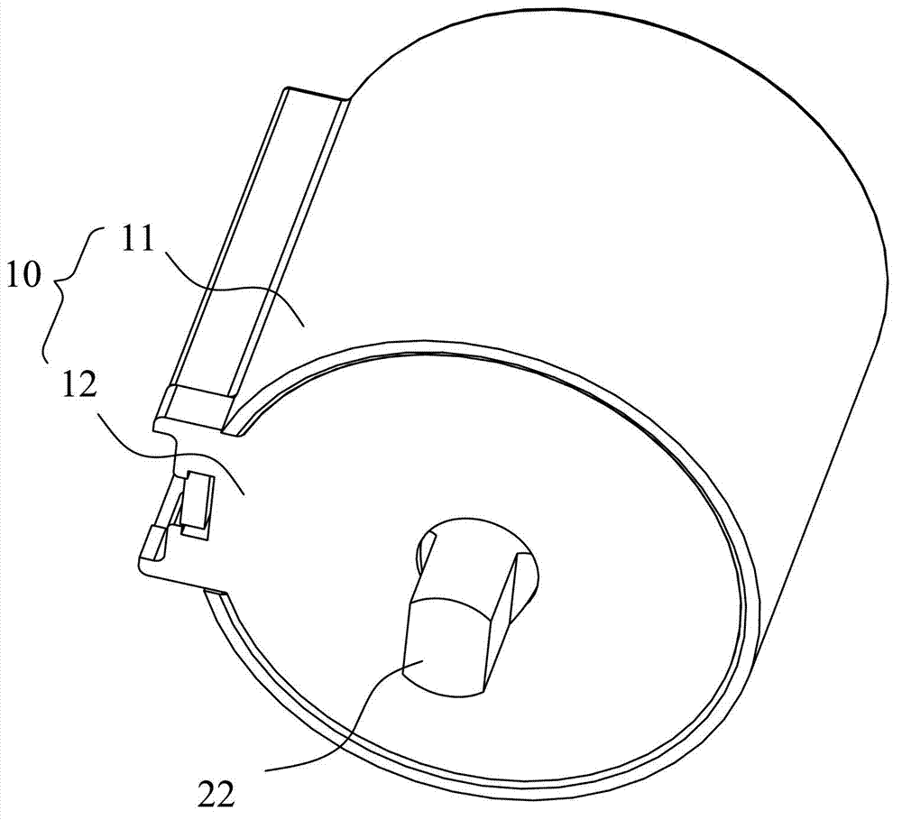
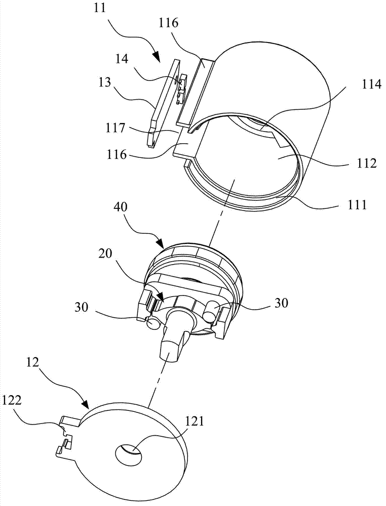
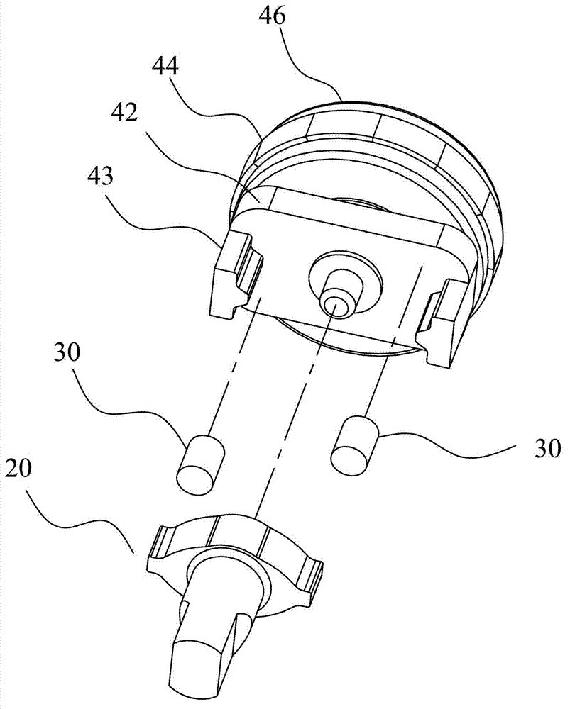
[0073] Please refer to Figure 1 to Figure 14 As shown, it shows the specific structure of the first embodiment of the present invention, the clutch includes a stationary housing 10 and a clutch assembly that rotates in the housing 10, the clutch assembly includes a driving member 20, a slide block 30, Driven part 40, wherein the driving part 20 is used as a driving wheel, a motor is connected to the reduction box and then connected to the driving part 20, the driven part 40 is used as a driven wheel, the driving part 20 is concentrically connected with the driven part 40, the driving part 20 drives the driven member 40 to rotate through the slide block 30 rotatably adsorbed on the driving member 20. When the clutch is “closed”, the driving member 20, the slide block 30 and the driven member 40 rotate synchronously.

[0074] Among them, such as figure 1 and figure 2 As shown, the housing 10 is cylindrical and includes a housing main body 11 and a cover body 12. The housing ...


PUM


Abstract

The invention discloses a built-in clutch and a combined motor with the same. The clutch comprises a fixed shell and a clutch component in the shell. The shell comprises a shell body and a cover. The clutch component comprises a magnetic drive member, a non-magnetic driven member and a magnetic slider. The drive member and the driven member are connected concentrically. The drive member is a cam structure with first clamping parts on the outer side. The first clamping parts can drive the slider to rotate and guarantee that the slider does not move radially. The driven member is provided with at least one drive block relative to the outer side of the cam. The inner side of the drive block is provided with second clamping parts. The shell adjacent to the drive member is provided with a magnetic inner annular face. The end face of the slider always attaches to the inner annular face of the shell. The side of the slider always attaches to on the inner side wall between the first clamping parts. When the clutch is closed, the slider is located between the first clamping parts and the second clamping parts, and the drive member can drive the driven member to rotate simultaneously.

Description

technical field [0001] The invention relates to the technology in the field of small clutches and micro-combined motor technology, in particular to a built-in clutch and a multifunctional combined motor with the clutch. Background technique [0002] Combined motor is a trend in the development of modern technology. The remarkable feature of micro-combined motor is to combine all motor parts into a whole with the same outer diameter as the motor. The most common combined motors are geared motors with gearboxes and tubular motors; With the continuous development of science and technology, people have higher and higher requirements for the function of the motor. The design of many products requires consideration of the special operation scheme in the case of power failure, so it is necessary to add a clutch to the motor; The deceleration motor and the clutch are designed and installed separately, which not only increases the cost, but also increases the radial space of the moto...

Claims


Application Information

Patent Timeline
Patent Type & Authority Applications(China)
IPC IPC(8): F16D27/01H02K7/108
Inventor 高林发
Owner 湖州荣辉进出口有限公司
Why Eureka
Try Eureka