Universal mounting brackets for attaching a hot injection manifold to the lower die set of an injection blow molding machine

a technology of injection manifolds and mounting brackets, which is applied in the direction of rigid containers, lightening support devices, furniture parts, etc., can solve the problems of affecting the distribution of molten materials in the parison cavity, material cost consideration, and high cost, so as to reduce heat loss from the manifold block

Inactive Publication Date: 2009-01-27
R & D TOOL & ENG
View PDF11 Cites 4 Cited by
  • Summary
  • Abstract
  • Description
  • Claims
  • Application Information

AI Technical Summary

Benefits of technology

[0003]Hot runner manifold blocks are used to deliver molten plastic material from the injection unit to multiple parison cavities at the injection station. The manifold block typically comes in a variety of designs and styles, but an important goal of each style is to achieve balanced flow of the molten material evenly to all of the parison cavities. Achieving balanced flow is critical to the stability of the bottle-making process and the uniform dimensional and distribution attributes of the bottles produced on the machine.
[0006]The intent of the present invention is to eliminate the base plate and replace it with a set of relatively small mounting brackets made of a low thermally conductive material to minimize heat loss from the manifold block. The design, shape and dimensions of the brackets can be standardized to serve manifold blocks of a standard width but various lengths in accordance with variations in the number of parison cavities involved.

Problems solved by technology

Such heat loss is a direct drain of manifold block heat in the contacted areas and can adversely affect the distribution of molten material to the parison cavities even in the best of manifold block designs.
While each manifold block and base plate can be designed such that their points of mutual contact optimize thermal characteristics within the space available at the injection station, this is an expensive, time-consuming undertaking.
Moreover, material cost is a consideration due to the relatively large size of current base plates.

Method used


Image

  • Universal mounting brackets for attaching a hot injection manifold to the lower die set of an injection blow molding machine
  • Universal mounting brackets for attaching a hot injection manifold to the lower die set of an injection blow molding machine
  • Universal mounting brackets for attaching a hot injection manifold to the lower die set of an injection blow molding machine

Examples


Embodiment Construction

[0015]The present invention is susceptible of embodiment in many different forms. While the drawings illustrate and the specification describes certain preferred embodiments of the invention, it is to be understood that such disclosure is by way of example only. There is no intent to limit the principles of the present invention to the particular disclosed embodiments.

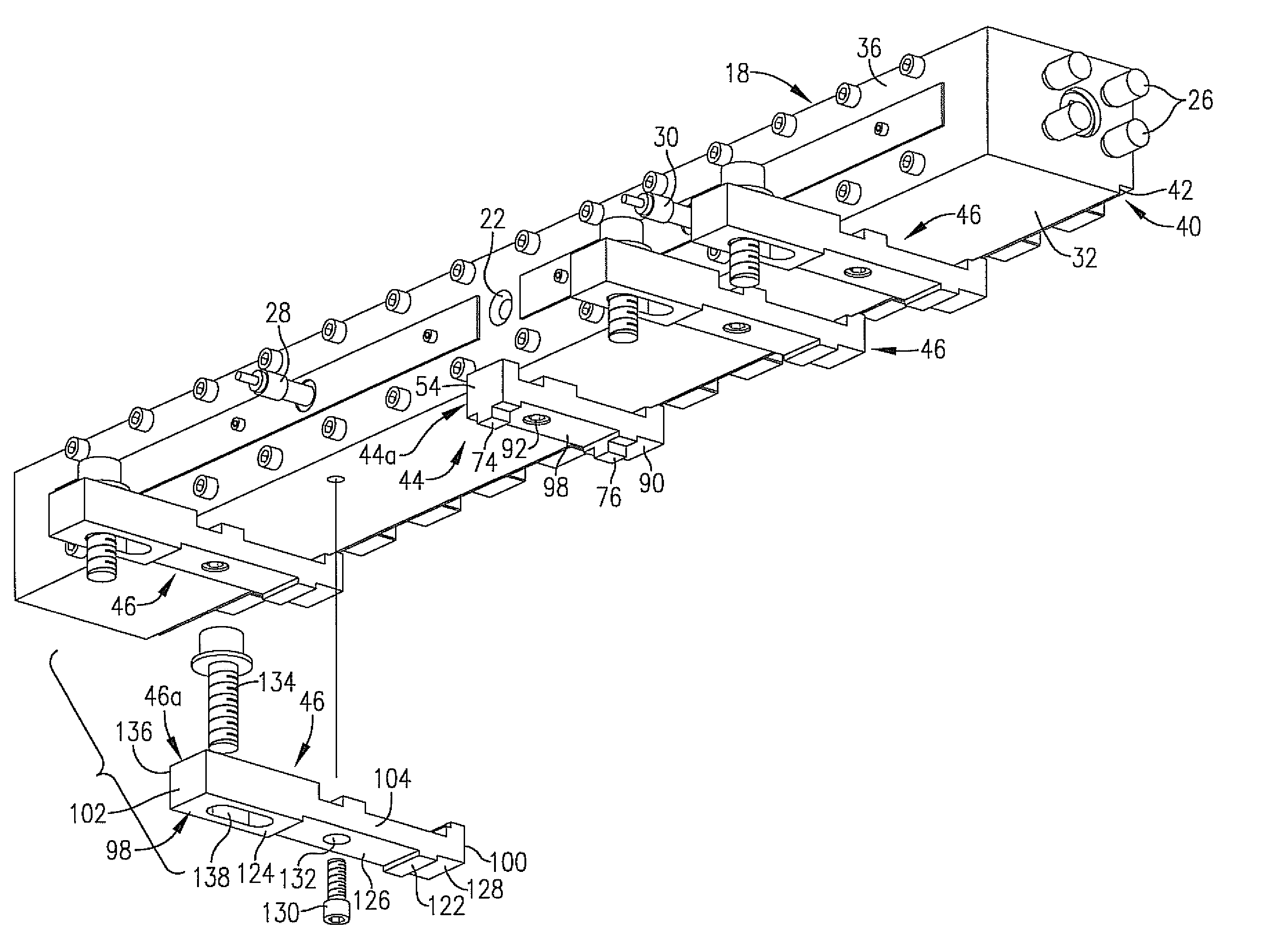
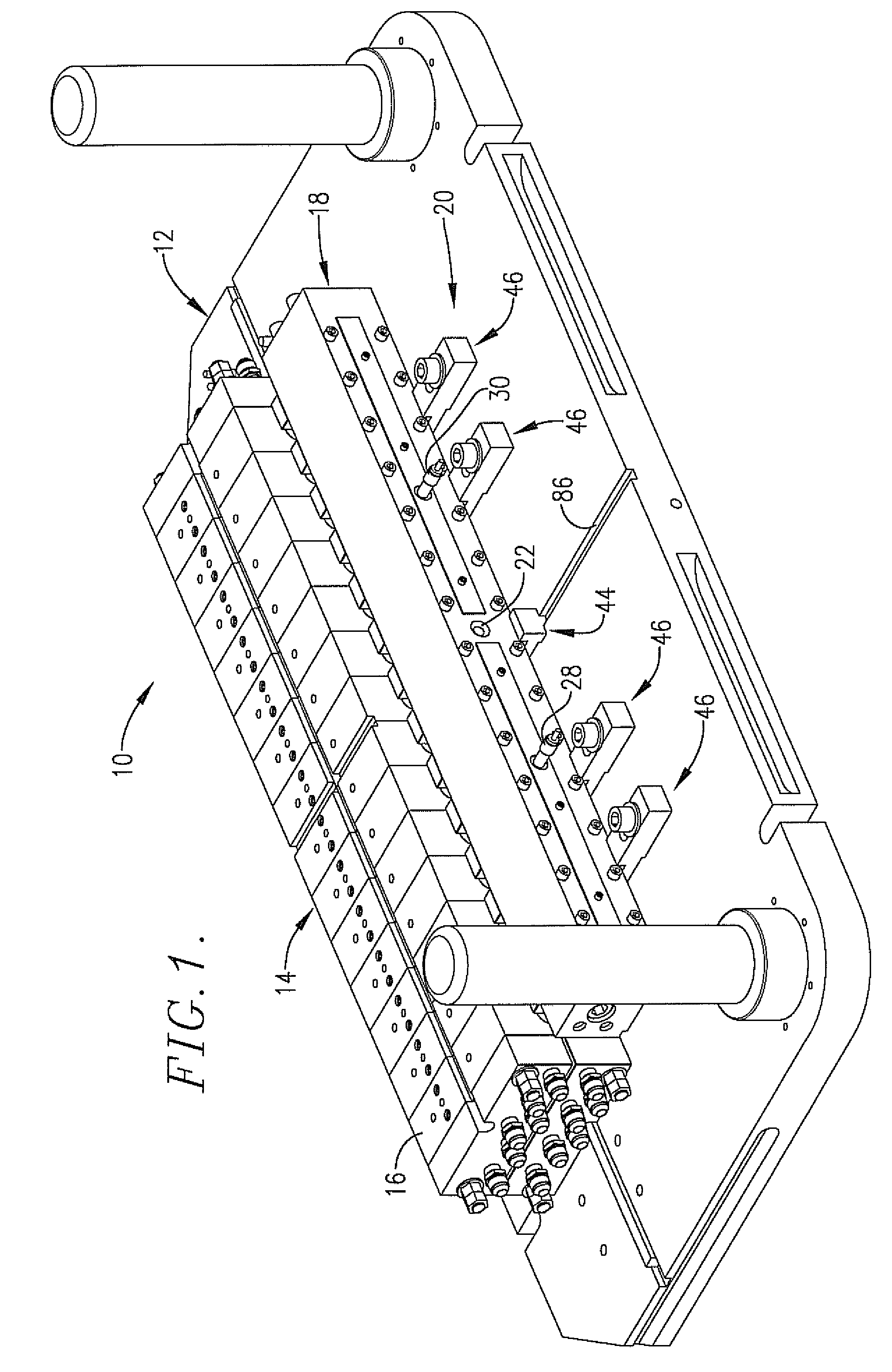
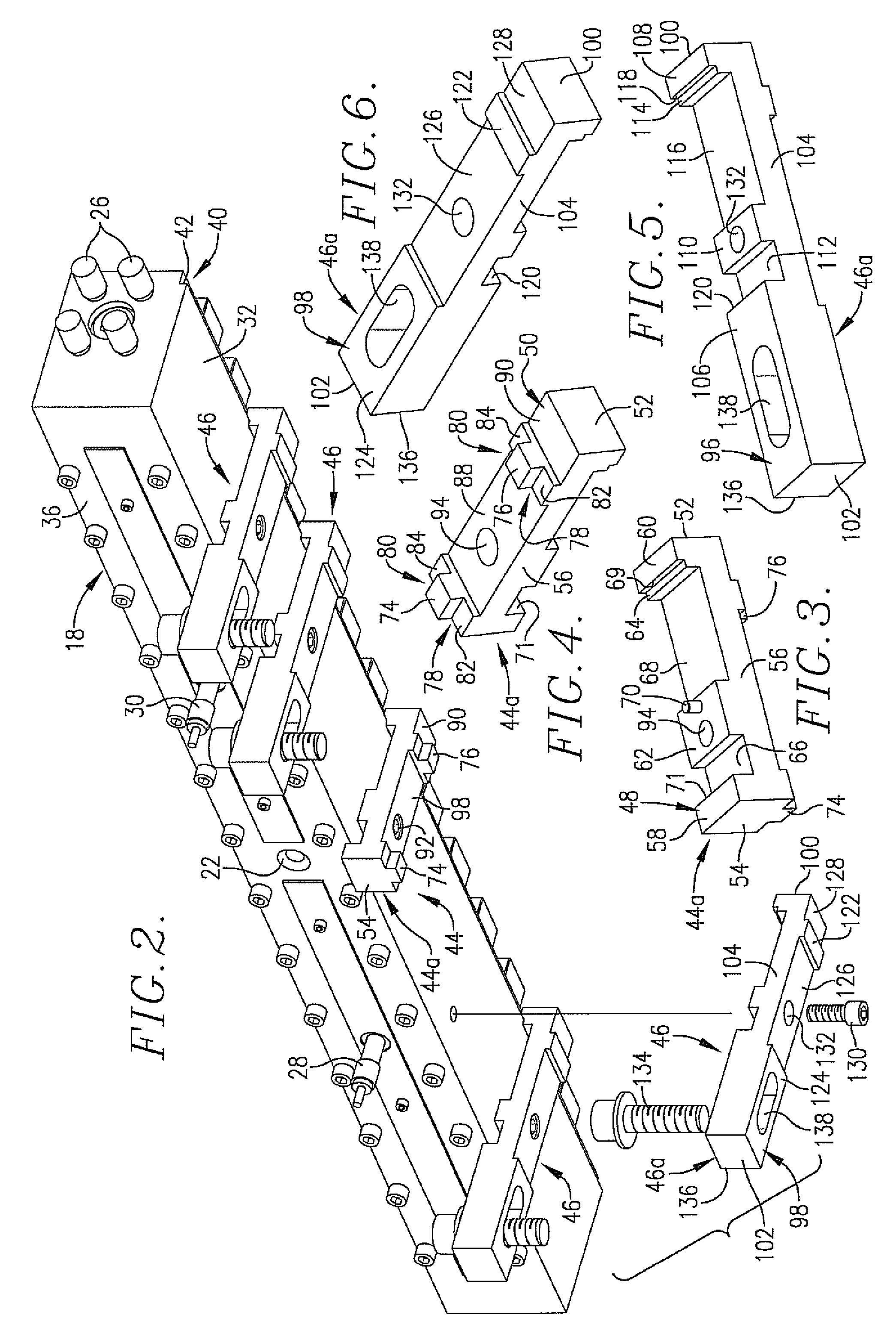
[0016]FIG. 1 illustrates in part the injection station 10 of an injection blow molding machine. The upper machine die set is removed in FIG. 1 for clarity, leaving the lower machine die set 12. A series of molds 14, each comprising an upper mold half 16 and a lower mold half (obstructed from view in the drawings) comprise part of the tooling at injection station 10 for use in producing parisons that will be blown into bottles. Upper mold halves 16 are secured to the upper machine die set for movement therewith as the molds open and close, while the lower mold halves are secured to lower die set 12. A manifold block 18 ...


PUM

PropertyMeasurementUnit
lengthaaaaaaaaaa
widthaaaaaaaaaa
stabilityaaaaaaaaaa

Abstract

Tooling for the injection station of an injection blow molding machine includes a set of individual mounting bracket assemblies that attach an elongated manifold block to the lower die set of the machine. The relatively slender brackets are designed to have minimal thermal contact with the manifold block without sacrificing stability and structural integrity. Standard sizes of the brackets maybe manufactured in advance to accommodate manifold blocks of different lengths but standard widths.

Description

RELATED APPLICATION[0001]This application is related to and claims the priority benefit of prior U.S. Provisional Application No. 60 / 782,187 filed Mar. 14, 2006, said Provisional Application being hereby incorporated by reference into the present specificationTECHNICAL FIELD[0002]The present invention relates to the field of injection blow mold tooling and, in particular, to the way in which a hot runner manifold block is secured to the lower die set at the injection station of an injection blow mold machine.BACKGROUND AND SUMMARY[0003]Hot runner manifold blocks are used to deliver molten plastic material from the injection unit to multiple parison cavities at the injection station. The manifold block typically comes in a variety of designs and styles, but an important goal of each style is to achieve balanced flow of the molten material evenly to all of the parison cavities. Achieving balanced flow is critical to the stability of the bottle-making process and the uniform dimensiona...

Claims


Application Information

Patent Timeline
Patent Type & Authority Patents(United States)
IPC IPC(8): B29C45/22
CPCB29C45/2725
Inventor CHEN, JINCHENG
Owner R & D TOOL & ENG
Why Eureka
Try Eureka