
Air conditioner for vehicle

a technology for air conditioners and vehicles, applied in vehicle maintenance, vehicle cleaning, transportation and packaging, etc., can solve problems such as insufficient effect, and achieve the effect of reducing noise and reducing the vibration of the air conditioner cas

Inactive Publication Date: 2009-01-27
DENSO CORP
View PDF12 Cites 6 Cited by
  • Summary
  • Abstract
  • Description
  • Claims
  • Application Information

AI Technical Summary

Benefits of technology

The present invention relates to an air conditioner for a vehicle that can reduce noises by reducing the vibration of the air conditioning case. The invention includes an air conditioning case, a functional member, an outside wall member, and a coupling part. The outside wall member is located across the central line of the functional member and is integrated with the side wall of the air conditioning case. This helps to reduce the surface vibration of the air conditioning case, relative to vibrations from the functional member and the engine room. The outside wall member can have a stepped part, a curved part, or a combination of both to have a variation in the clearance in the air flow direction. The coupling part can be constructed of ribs or a combination of ribs and a check opening for checking the state of the fastening screw. The air conditioner can be constructed of a plurality of case parts that are joined together by a joining part. The outside wall members can be provided with openings for cooling molds and joined together at the outer side of the side wall. The technical effects of the invention are to reduce noises and vibrations in the air conditioning case, which improves the overall performance of the air conditioner for vehicles.

Problems solved by technology

However, the above-mentioned conventional air conditioner for a vehicle can produce a measure of effect in inhibiting the occurrence of noises by reducing the vibration of surface of the air conditioning case but cannot produce a sufficient effect.

Method used


Image

  • Air conditioner for vehicle
  • Air conditioner for vehicle
  • Air conditioner for vehicle

Examples


first embodiment

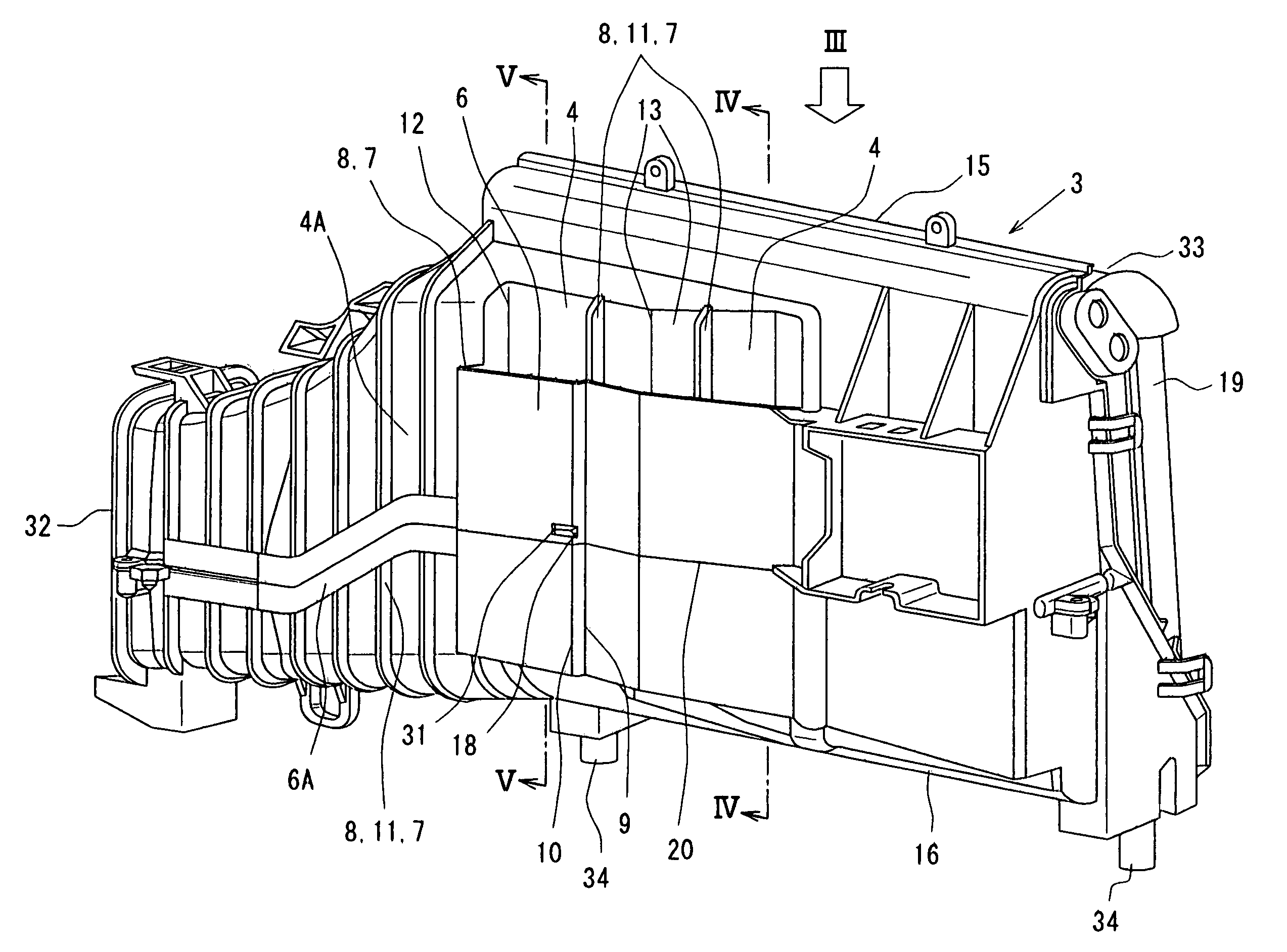
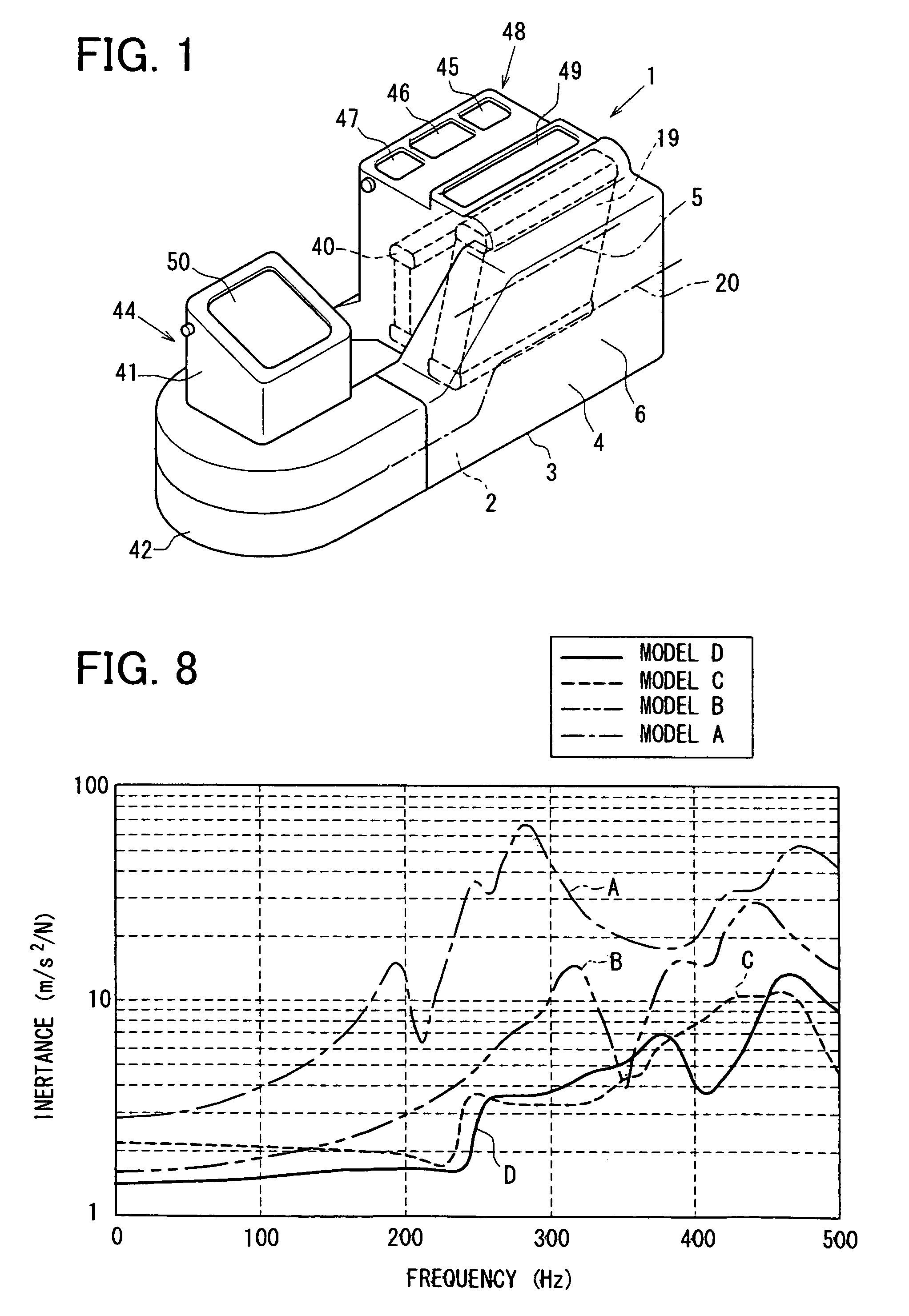
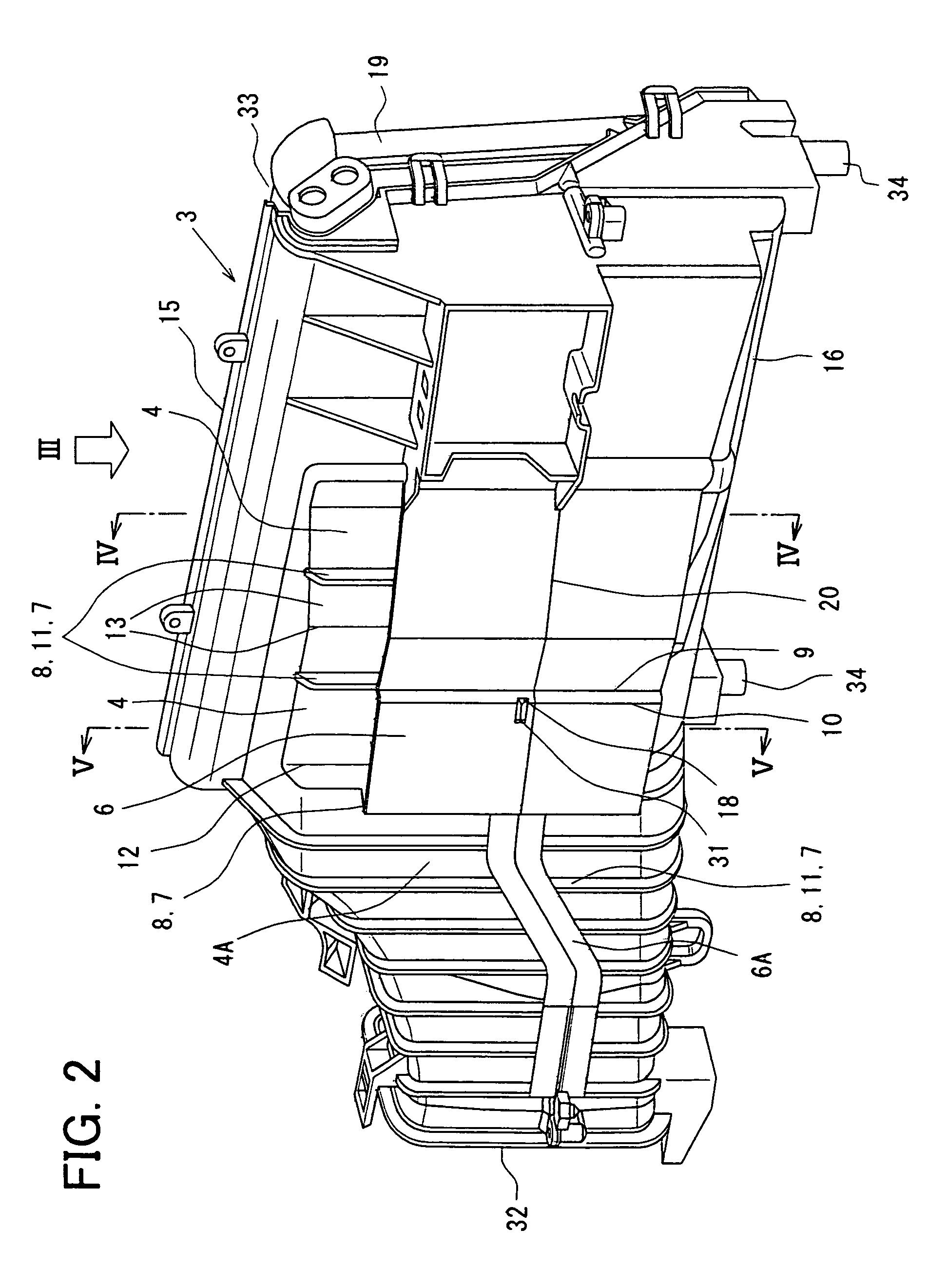
[0023]Hereinafter, the first embodiment will be described by the use of FIG. 1 to FIG. 5 and FIG. 8. FIG. 1 is a schematic diagram showing the general construction of an air conditioning unit of an air conditioner for a vehicle in this embodiment.

[0024]An air conditioner of this embodiment is used for a vehicle for private use or for commercial use and is constructed in such a way that air conditioning in a vehicle compartment can be controlled automatically by a control device or manually. This air conditioning device 1 of an air conditioner for a vehicle is fixed to the side wall surface of a dash panel for separating the engine room on the front side of the vehicle from the vehicle compartment. Moreover, it is also recommendable to employ construction in which the air conditioning device 1 is arranged in a rear trunk room.

[0025]As shown in FIG. 1, the air conditioning device 1 is provided with an intake unit 44, an air conditioning unit 48, and a duct (corresponding to a part of ...

second embodiment

[0061]This embodiment is different from the air conditioner for a vehicle of the first embodiment in that the shape of the air conditioning case is different from each other, and is the same as the air conditioner in the other construction. Here, the same construction is denoted by the same reference symbols in FIG. 6 and FIG. 7 and its description will be omitted. FIG. 6 is a perspective view showing the construction of an air conditioning case of this embodiment. FIG. 7 is a perspective view showing the shape of the cut end when the air conditioning case is cut along the line VII-VII in FIG. 6.

[0062]As shown in FIG. 6 and FIG. 7, a plurality of outside wall members 22, 23 are arranged outside the side wall 4 of an air conditioning case 3A with a clearance created between them and on both sides sandwiching the combining part 21 of the air conditioning case 3A. Each of the outside wall members 22, 23 are integrated with the side wall 4 by a lattice-shaped rib 24 as a coupling part, ...


PUM


Abstract

An air conditioner includes an air conditioning case for defining an air passage through which air flows into a vehicle compartment, a functional member located in the air conditioning case for performing air conditioning of the vehicle compartment, an outside wall member arranged outside a side wall of the air conditioning case to form a clearance with the side wall, and a coupling part through which the outside wall member is integrated with the side wall. In this air conditioner, the outside wall member is located across approximately a projected line of a central line of the functional member extending in a longitudinal direction of the functional member, projected onto the side wall. Therefore, a vibration of the air conditioning case can be reduced, and a noise generation can be effectively restricted.

Description

CROSS REFERENCE TO RELATED APPLICATION[0001]This application is based on Japanese Patent Application No. 2005-187014 filed on Jun. 27, 2005, the contents of which are incorporated herein by reference in its entirety.FIELD OF THE INVENTION[0002]The present invention relates to an air conditioner for a vehicle that blows conditioned air into a vehicle compartment of an automobile or the like.BACKGROUND OF THE INVENTION[0003]In a conventional air conditioner for a vehicle, generally, an air conditioning unit for adjusting air to be blown off into a vehicle compartment is surrounded by an air conditioning case and is mounted to a dash panel for separating the vehicle compartment from the engine room of the vehicle. Hence, there are cases where vibrations caused by the engine and a functional member for air conditioning such as an evaporator are transmitted to the air conditioning case via the dash panel to vibrate the side walls of the air conditioning case to thereby make noises.[0004]...

Claims


Application Information

Patent Timeline
Patent Type & Authority Patents(United States)
IPC IPC(8): B60H1/02
CPCB60H1/00514B60H1/00564B60H2001/006
Inventor OKUMURA, YOSHIHIKONAGAYA, SHIGEYOSHIMURAKI, TOSHIHIKO
Owner DENSO CORP
Learn More