
Power supply apparatus for sliding structure

a technology for power supply apparatus and sliding structure, which is applied in the direction of insulated conductors, cables, coupling device connections, etc., to achieve the effects of reducing the size of the power supply apparatus, and increasing the flexibility of the layout of the auxiliary devices at the sliding structur

Active Publication Date: 2009-01-27
YAZAKI CORP +1
View PDF9 Cites 20 Cited by
  • Summary
  • Abstract
  • Description
  • Claims
  • Application Information

AI Technical Summary

Benefits of technology

This design reduces the size of the power supply apparatus, increases flexibility in auxiliary device layout, improves durability by minimizing bending stress on the wiring harness, and lowers costs by eliminating the need for expensive covers, while ensuring reliable power supply and smooth operation.

Problems solved by technology

The above problems occur not only in the sliding door 62 of the car, but also in a case that the power supply apparatus mentioned above is applied on any sliding structures such as a sliding door for a vehicle and a sliding door for manufacturing machine.

Method used


Image

  • Power supply apparatus for sliding structure
  • Power supply apparatus for sliding structure
  • Power supply apparatus for sliding structure

Examples


first embodiment

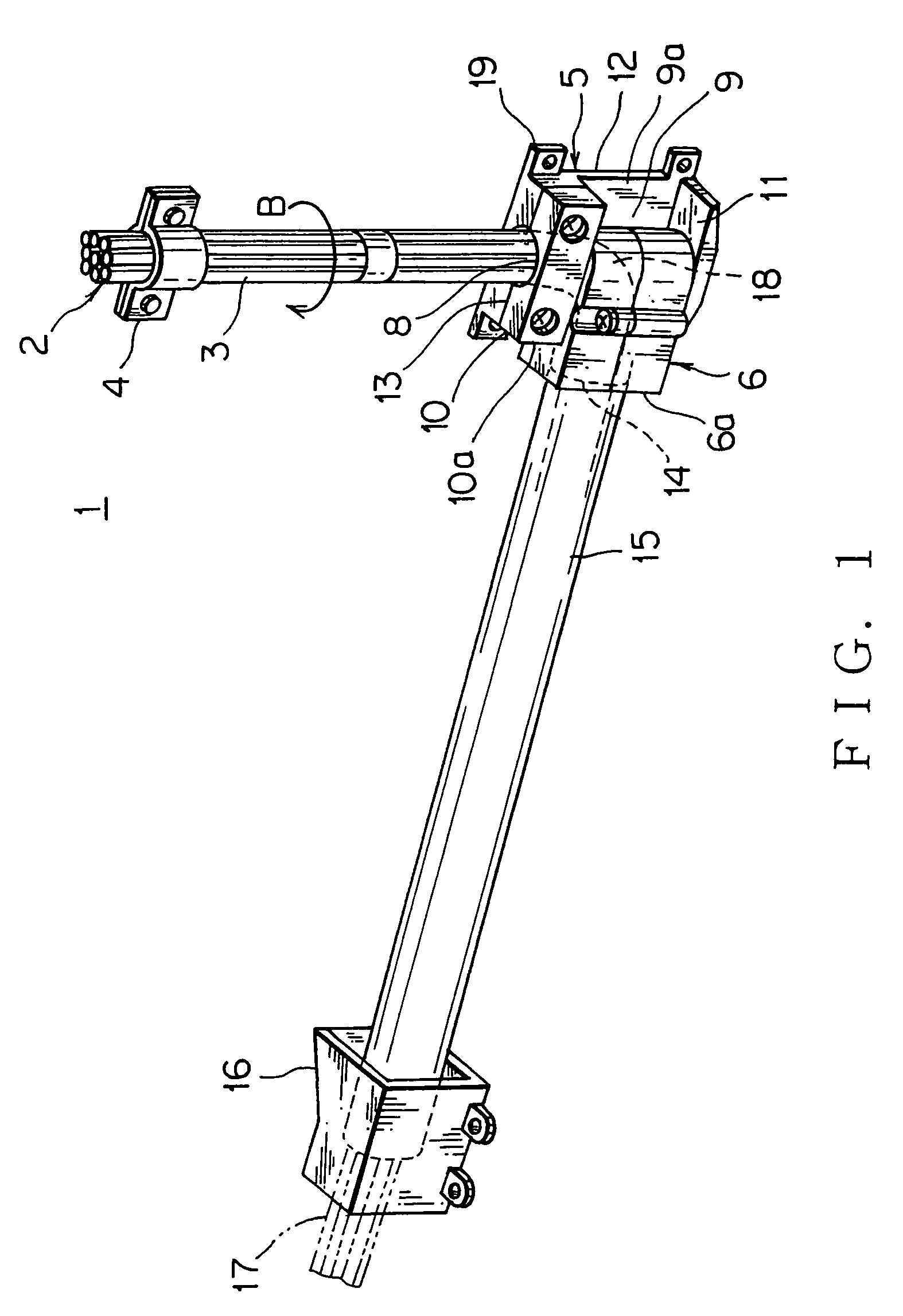
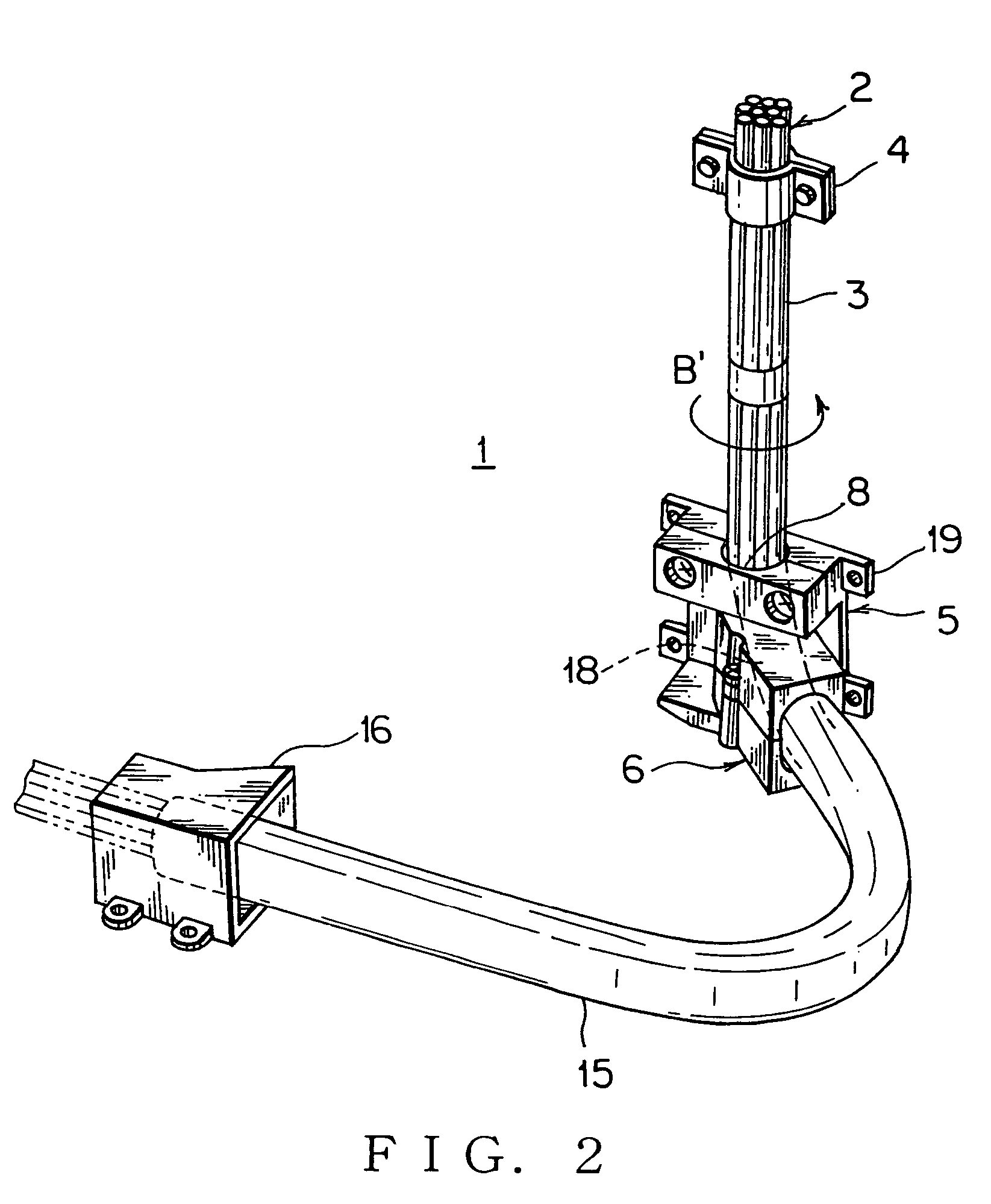
[0053]FIGS. 1, 2 show a power supply apparatus for a sliding structure according to the present invention.

[0054]The power supply apparatus 1 for the sliding structure includes a wiring harness 2 (a plurality of electric wires) having a vertical path portion 3, a harness fixing member 4 made of synthetic resin or metal for fixing the vertical path portion 3 arranged vertically on the sliding door of a car (sliding structure), a fixed base 5 made of synthetic resin and arranged after the vertical path portion 3, and a swing member 6 made of synthetic resin and supported pivotably in a horizontal plane by the fixed base 5.

[0055]The harness fixing member 4 in the embodiment is a curved plate clamp for clamping and fixing the electric wires of the wiring harness 2 on a door panel with a bolt or a lock pin. The harness fixing member 4 is not limited only to this clamp, but also any-type fixing member, such as a band or a adhesive tape, for fixing a top end of the vertical path portion 3 o...

third embodiment

[0062]The harness fixing unit 16 is rigidly fixed on the car body with a plurality of bolts. The harness fixing unit 16 will be described later in detail in a The wiring harness 2 is wired horizontally from the swing member 6 to the harness fixing unit 16.

[0063]FIG. 1 shows a complete closed condition, in which the sliding door (not shown) is closed forwardly. The harness fixing member 4 and the fixed base 5 fixed on the sliding door move forwardly to be integrated with the sliding door. Thereby, the swing member 6 pivots slantwise rearwardly about the top and bottom axial portions (not shown), and the vertical path portion 3 of the wiring harness 2 is twisted in a round or axial direction as shown in an arrow B (clockwise in FIG. 1) between the harness fixing member 4 and the swing member 6 to absorb the pivoting motion of the swing member 6. A horizontal portion (protecting tube 15) of the wiring harness 2 is pulled rearwardly to extend straightly between the swing member 6 and t...

second embodiment

[0066]FIGS. 3, 4 show a power supply apparatus for a sliding structure according of the present invention.

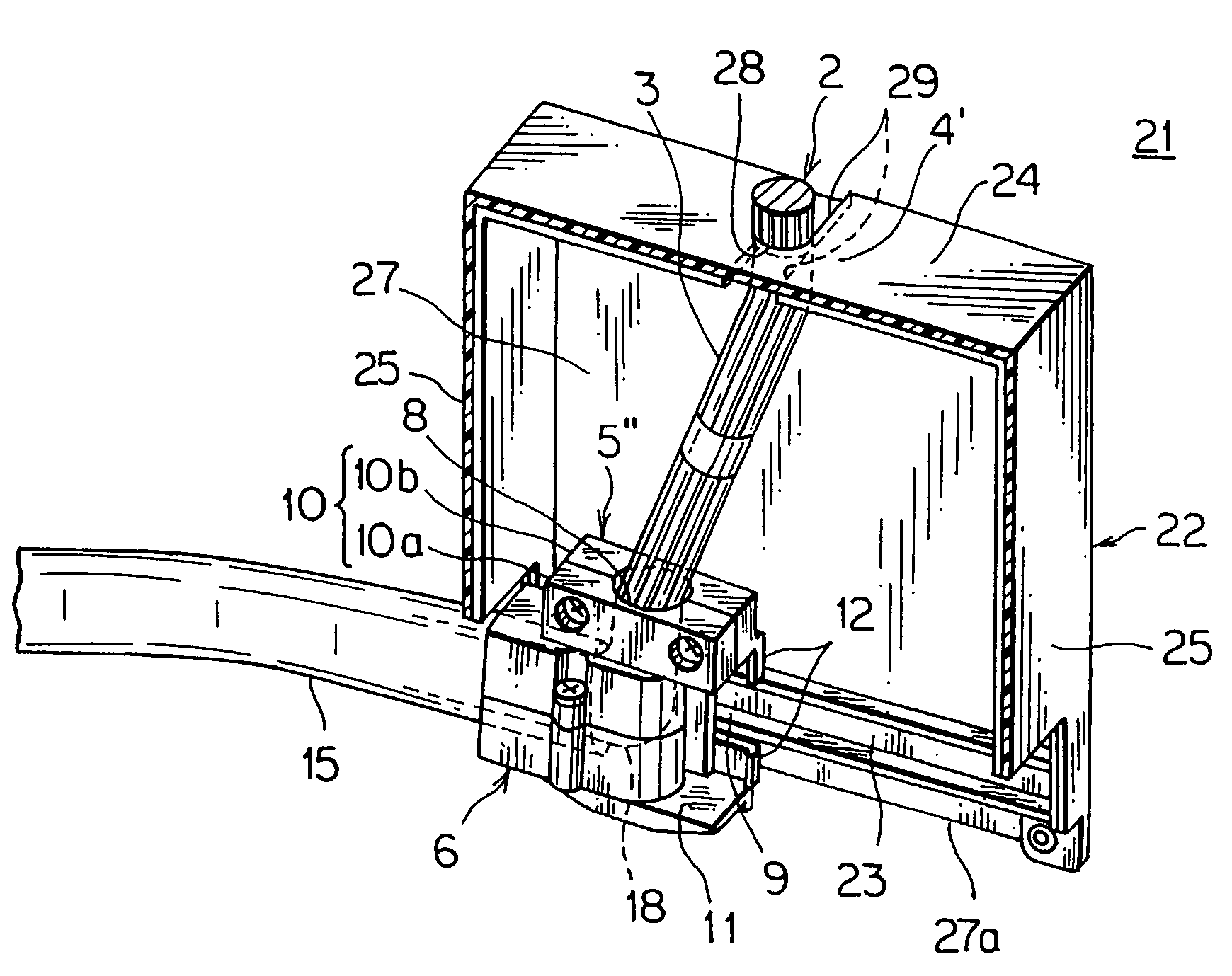
[0067]The power supply apparatus 1′ for the sliding structure includes a wiring harness 2 (a plurality of electric wires) having a vertical path portion 3, a harness fixing member 4 made of synthetic resin or metal for fixing the vertical path portion 3 arranged vertically on the sliding door of a car (sliding structure), a pendulum-like movable base 5′ made of synthetic resin and arranged after the vertical path portion 3, and a swing member 6 made of synthetic resin and supported pivotably in a horizontal plane by the movable base 5. The movable base 5′ is modified by removing a bracket 19 from the fixed base 5 of the first embodiment.

[0068]The harness fixing member 4 in the embodiment is a curved plate clamp for clamping and fixing the electric wires of the wiring harness 2 on a door panel with a bolt or a lock pin. The harness fixing member 4 is not limited only to this clam...


PUM

PropertyMeasurementUnit
movable angleaaaaaaaaaa
lengthaaaaaaaaaa
rotation angleaaaaaaaaaa

Abstract

A power supply apparatus for a sliding structure, which can be arranged in a small space in the sliding structure, the power supply apparatus including a wiring harness having a vertical path portion; a harness fixing member for fixing one end of the vertical path portion of the wiring harness on the sliding structure; a fixed base fixed on the sliding structure for holding the other end of the vertical path portion; and a swing member mounted on the fixed base to swing freely in a horizontal plane for allowing the vertical path portion to be twisted along a circumferential direction of itself and leading a part of the wiring harness continued to the vertical path portion toward a fixed structure. Instead of the fixed base, a movable base 5′, and a guide rail to be engaged with the movable base can be applied.

Description

[0001]The priority application Number Japan Patent Application 2005-308099 upon which this patent application is based is hereby incorporated by reference.BACKGROUND OF THE INVENTION[0002]1. Field of the Invention[0003]This invention relates to a power supply apparatus for a sliding structure, which is mounted on the sliding structure such as a sliding door of a vehicle and supplies power continuously to an auxiliary device at the sliding structure.[0004]2. Description of the Related Art[0005]FIGS. 17, 18 show one embodiment of a usual power supply apparatus for a sliding door (refer to Patent Document 1).[0006]The power supply apparatus 61 for the sliding door includes a long sideways guide member 63 mounted on a sliding door 62 of a car, a slider 64 engaging slidably with a rail portion of the guide member 63, a swing member 65 (FIG. 18) supported pivotably in a horizontal plane by a shaft vertical to the slider 64 and a caterpillar-like harness cover 66, which is bent into U-shap...

Claims


Application Information

Patent Timeline
Patent Type & Authority Patents(United States)
IPC IPC(8): H01B7/00H01B7/06H01R33/00H02G3/04
CPCB60R16/0215
Inventor KISU, NAOMINISHIJIMA, MASATAKA
Owner YAZAKI CORP
Learn More