Power supply apparatus for sliding structure
a technology for power supply apparatus and sliding structure, which is applied in the direction of insulated conductors, cables, coupling device connections, etc., to achieve the effects of reducing the structure size of the power supply apparatus, reducing the size of the structure, and increasing the flexibility of the layout of the auxiliary devices at the sliding structur
- Summary
- Abstract
- Description
- Claims
- Application Information
AI Technical Summary
Benefits of technology
Problems solved by technology
Method used
Image
Examples
first embodiment
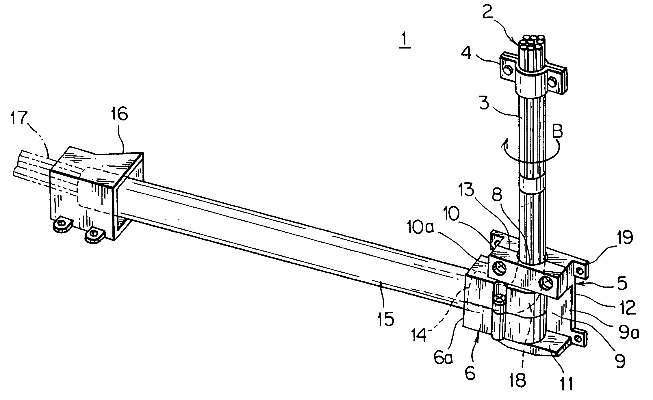
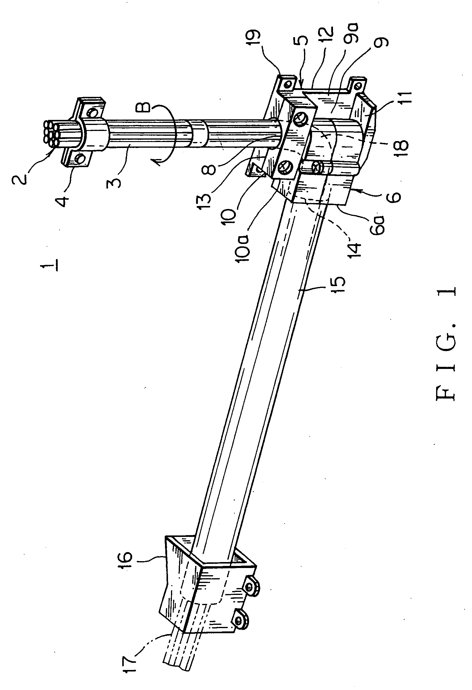
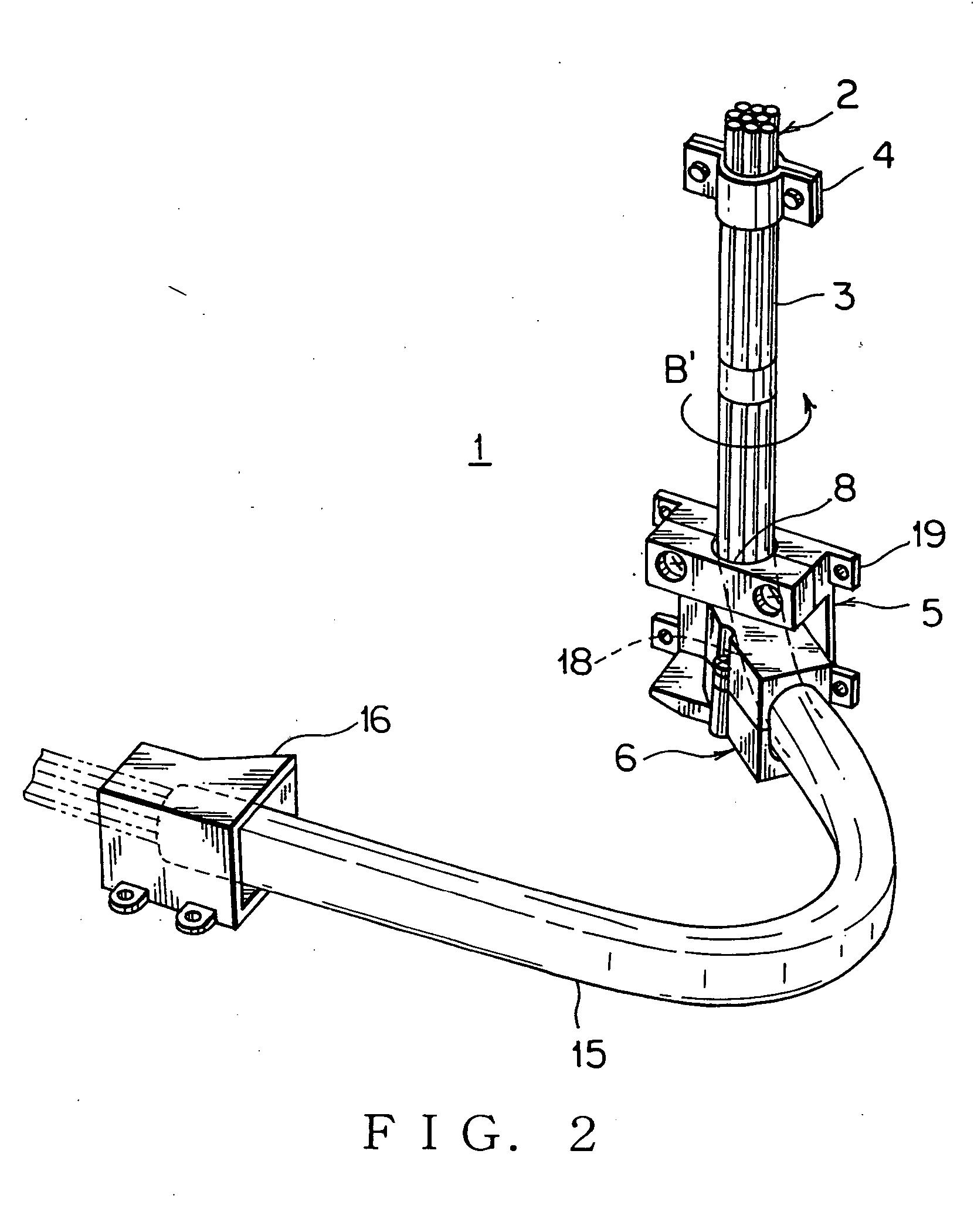
[0053]FIGS. 1, 2 show a power supply apparatus for a sliding structure according to the present invention.
[0054] The power supply apparatus 1 for the sliding structure includes a wiring harness 2 (a plurality of electric wires) having a vertical path portion 3, a harness fixing member 4 made of synthetic resign or metal for fixing the vertical path portion 3 arranged vertically on the sliding door of a car (sliding structure), a fixed base 5 made of synthetic resin and arranged after the vertical path portion 3, and a swing member 6 made of synthetic resin and supported pivotably in a horizontal plane by the fixed base 5.
[0055] The harness fixing member 4 in the embodiment is a curved plate clamp for clamping and fixing the electric wires of the wiring harness 2 on a door panel with a bolt or a lock pin. The harness fixing member 4 is not limited only as the this clamp, but also any-type fixing member, such as a band or a adhesive tape, for fixing a top end of the vertical path por...
third embodiment
[0062] The harness fixing unit 16 is rigidly fixed on the car body with a plurality of bolts. The harness fixing unit 16 will be described later in detail in a The wiring harness 2 is wired horizontally from the swing member 6 to the harness fixing unit 16.
[0063]FIG. 1 shows a complete close condition, in which the sliding door (not shown) is closed forwardly. The harness fixing member 4 and the fixed base 5 fixed on the sliding door move forwardly to be integrated with the sliding door. Thereby, the swing member 6 pivots slantwise rearwardly about the top and bottom axial portions (not shown), and the vertical path portion 3 of the wiring harness 2 is twisted in a round direction as shown in an arrow B (clockwise in FIG. 1) between the harness fixing member 4 and the swing member 6 to absorb the pivoting motion of the swing member 6. A horizontal portion (corrugate tube 15) of the wiring harness 2 is pulled rearwardly to extend straightly between the swing member 6 and the harness...
second embodiment
[0066]FIGS. 3, 4 show a power supply apparatus for a sliding structure according to the present invention.
[0067] The power supply apparatus 1′ for the sliding structure includes a wiring harness 2 (a plurality of electric wires) having a vertical path portion 3, a harness fixing member 4 made of synthetic resign or metal for fixing the vertical path portion 3 arranged vertically on the sliding door of a car (sliding structure), a pendulum-like movable base 5′ made of synthetic resin and arranged after the vertical path portion 3, and a swing member 6 made of synthetic resin and supported pivotably in a horizontal plane by the movable base 5. The movable base 5′ is modified by removing a bracket 19 from the fixed base 5 of the first embodiment.
[0068] The harness fixing member 4 in the embodiment is a curved plate clamp for clamping and fixing the electric wires of the wiring harness 2 on a door panel with a bolt or a lock pin. The harness fixing member 4 is not limited only as the t...
PUM
 Abstract
Description
Claims
Application Information
 - R&D
- Intellectual Property
- Life Sciences
- Materials
- Tech Scout
- Unparalleled Data Quality
- Higher Quality Content
- 60% Fewer Hallucinations
Browse by: Latest US Patents, China's latest patents, Technical Efficacy Thesaurus, Application Domain, Technology Topic, Popular Technical Reports.
© 2025 PatSnap. All rights reserved.Legal|Privacy policy|Modern Slavery Act Transparency Statement|Sitemap|About US| Contact US: help@patsnap.com


