Eureka AIR delivers breakthrough ideas for toughest innovation challenges, trusted by R&D personnel around the world.

Detecting a thermal asperity condition of a disk drive head responsive to data value transitions

Inactive Publication Date: 2009-01-27
MAXTOR
View PDF5 Cites 9 Cited by
  • Summary
  • Abstract
  • Description
  • Claims
  • Application Information

AI Technical Summary

Benefits of technology

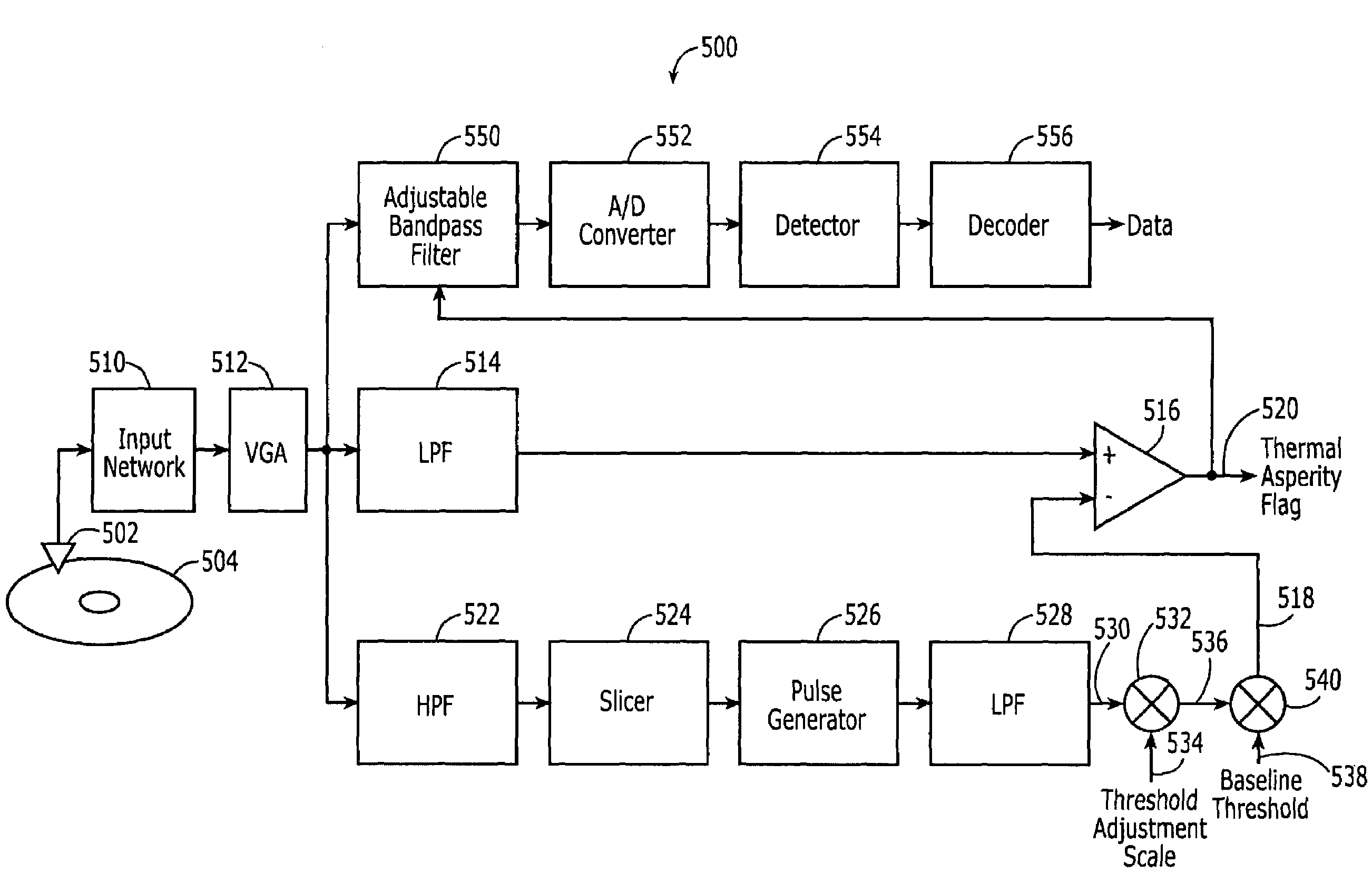
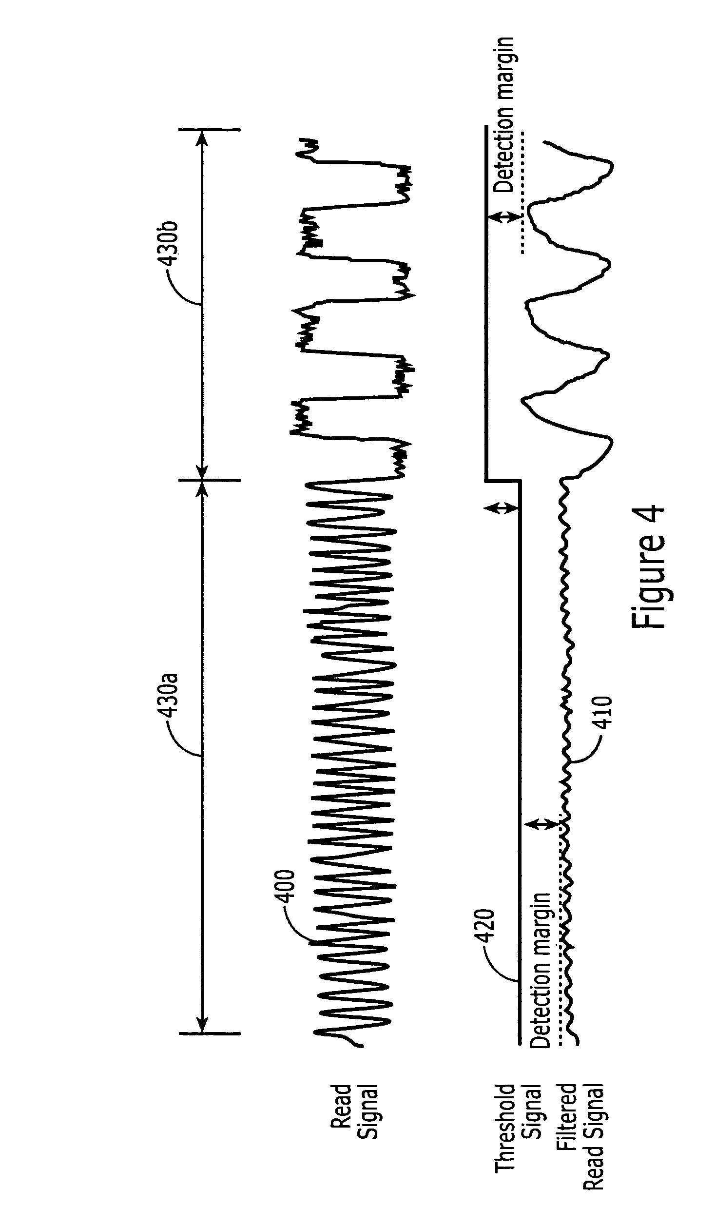
[0016]Some embodiments of the present invention are directed to a method of detecting a thermal asperity condition of a head in a disk drive. The head is configured to generate a read signal by reading data on a rotatable data storage disk in the disk drive. The read signal includes a data component and a thermal component. The read signal is compared to a thermal asperity threshold to detect occurrence of an excessive level of the thermal component of the read signal as a thermal asperity condition of the head. The thermal asperity threshold is varied in response to a rate of occurrence of data value transitions in the data component of the read signal. For example, in some embodiments, the thermal asperity threshold is increased in response to a decrease in the rate of occurrence of data value transitions, and the thermal asperity threshold is decreased in response to an increase in the rate of occurrence of data value transitions. By varying the thermal asperity threshold, the sensitivity of the thermal asperity detector may be improved to allow lower level thermal asperity conditions to be detected with increased accuracy.

Problems solved by technology

There are many operational variables that can adversely affect the read performance of a magnetic disk drive.
Among the variables, those which cause temperature variations in the MR element can be particularly troublesome.
Collisions between the asperities and the head cause the head to be further heated.
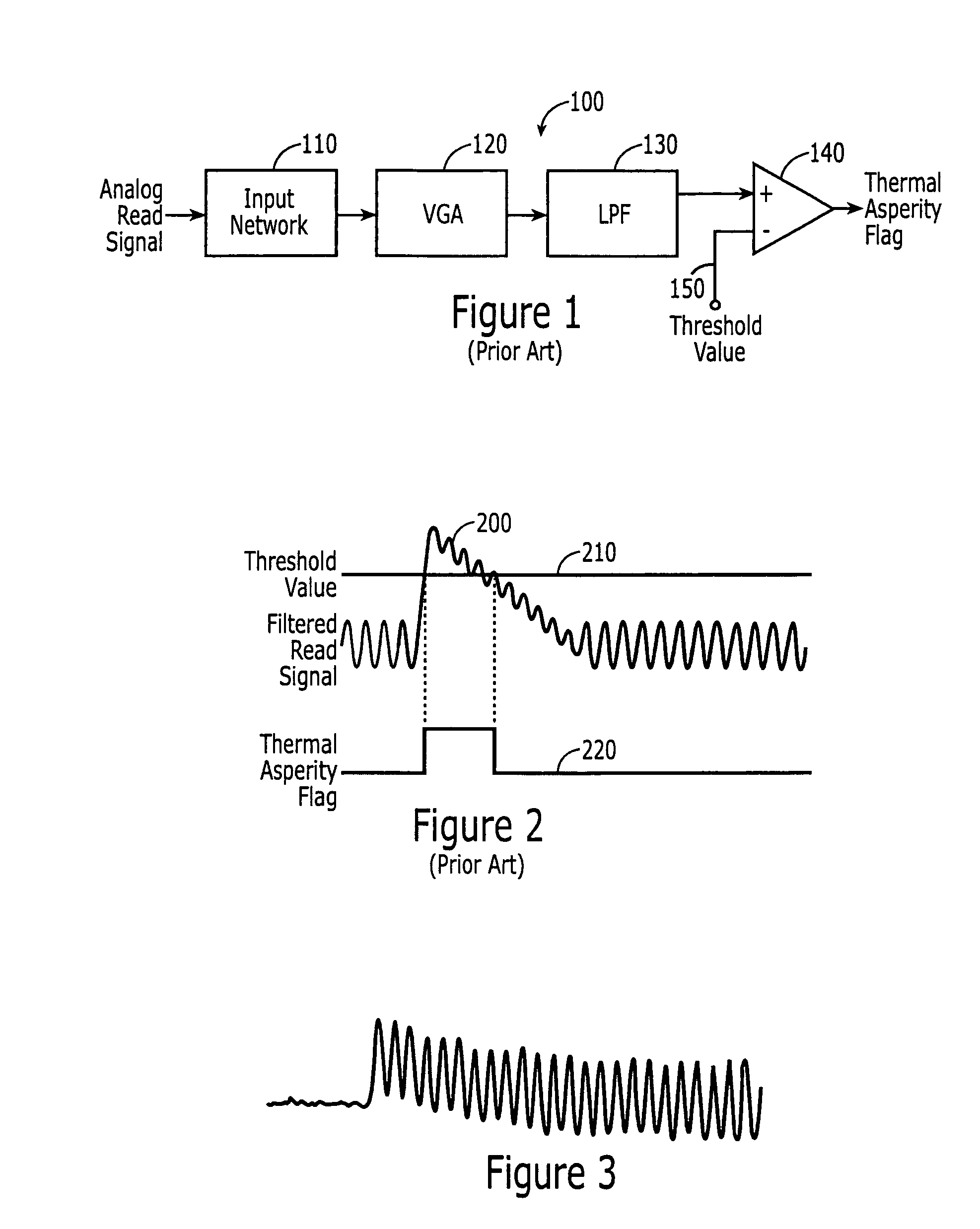
Accordingly, selecting a low threshold value can increase the sensitivity of the thermal asperity detector to detecting thermal asperity conditions, but it can also increase the occurrence of false indications of thermal asperity conditions when an insufficient margin is maintained between the data component of the filtered read signal and the threshold value.
Greater baseline wander may necessitate a greater margin which, correspondingly, may reduce the ability of a thermal asperity detector to detect small to medium indications of a thermal asperity condition of a head.

Method used


Image

  • Detecting a thermal asperity condition of a disk drive head responsive to data value transitions
  • Detecting a thermal asperity condition of a disk drive head responsive to data value transitions
  • Detecting a thermal asperity condition of a disk drive head responsive to data value transitions

Examples


Embodiment Construction

[0029]The present invention now will be described more fully hereinafter with reference to the accompanying figures, in which embodiments of the invention are shown. This invention may, however, be embodied in many alternate forms and should not be construed as limited to the embodiments set forth herein.

[0030]Accordingly, while the invention is susceptible to various modifications and alternative forms, specific embodiments thereof are shown by way of example in the drawings and will herein be described in detail. It should be understood, however, that there is no intent to limit the invention to the particular forms disclosed, but on the contrary, the invention is to cover all modifications, equivalents, and alternatives falling within the spirit and scope of the invention as defined by the claims. Like numbers refer to like elements throughout the description of the figures.

[0031]It will be understood that, as used herein, the term “comprising” or “comprises” is open-ended, and i...


PUM


Abstract

Methods are disclosed for detecting a thermal asperity condition of a head that is configured to generate a read signal by reading data on a rotatable data storage disk in a disk drive. The read signal includes a data component and a thermal component. The read signal is compared to a thermal asperity threshold to detect occurrence of an excessive level of the thermal component of the read signal as a thermal asperity condition of the head. The thermal asperity threshold is varied in response to a rate of occurrence of data value transitions in the data component of the read signal. The thermal asperity threshold can be increased in response to a decrease in the rate of occurrence of data value transitions, and can be decreased in response to an increase in the rate of occurrence of data value transitions. By varying the thermal asperity threshold, the sensitivity of the thermal asperity detector may be improved to allow lower level thermal asperity conditions to be detected with increased accuracy. Related disk drives are also disclosed.

Description

RELATED APPLICATION[0001]This application claims the benefit of and priority to U.S. Provisional Patent Application No. 60 / 717,901, filed Sep. 16, 2005, the disclosure of which is hereby incorporated herein by reference as if set forth in its entirety.FIELD OF THE INVENTION[0002]The present invention generally relates to magnetic data storage devices and, more particularly, to filtering a read signal in a magnetic data storage device.BACKGROUND OF THE INVENTION[0003]Disk drives are a common type of magnetic data storage device. Digital information is stored within concentric tracks on a storage disk which is coated with a magnetic material that is capable of changing its magnetic orientation in response to an applied magnetic field.[0004]During operation of a conventional disk drive, the disk is rotated about a central axis at a substantially constant rate. To read data from or write data onto the disk, a head is held close to a desired track of the disk while the disk is spinning. ...

Claims


Application Information

Patent Timeline
IPC IPC(8): G11B5/02
CPCG11B5/40
Inventor CHEN, JINGHUANPAVLAK, JR., RAYMONDLIU, JINGFENG
Owner MAXTOR
Why Eureka
Eureka Blog
Learn More