Method and apparatus for testing logic circuit designs

a logic circuit and logic circuit technology, applied in the field of logic circuit design testing, can solve the problems of large size of scan test pattern for today's large design, large size of scan test pattern generation, and complex testing of digital logic circuits

Inactive Publication Date: 2009-01-27
NEC CORP
View PDF10 Cites 22 Cited by
  • Summary
  • Abstract
  • Description
  • Claims
  • Application Information

AI Technical Summary

Problems solved by technology

Testing of complex digital logic circuits requires the generation of a large number of test patterns.
Unfortunately, the sizes of scan test patterns for today's large designs can be even larger than the sizes of a typical tester (i.e., an automated test equipment (ATE)) memory.
This necessitates multiple loading of test patterns during a test application and, in turn, increases test application time and test cost.
The oversized test pattern set problem is even more severe in delay testing, which has become a necessary test procedure for deep-sub micron chips.
Compression schemes that are independent of an automatic test pattern generator (ATPG), usually based on coding theory, have the disadvantage that the design of the decompressor is dependent on the actual test patterns.

Method used


Image

  • Method and apparatus for testing logic circuit designs
  • Method and apparatus for testing logic circuit designs
  • Method and apparatus for testing logic circuit designs

Examples


Embodiment Construction

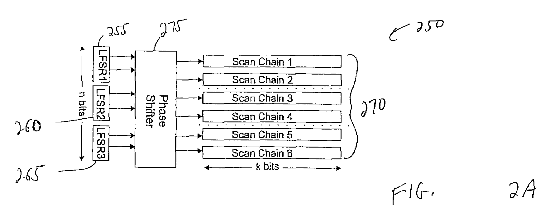
[0035]FIG. 2A is a block diagram of an embodiment of a decompressor 250 where three LFSRs 255, 260, 265 connected to scan chains 270 using a phase shifter 275. The sum of the stages of the LFSRs 255, 260, 265 is equal to SMAX+M, where SMAX is the maximum number of specified bits in any test cube (a test pattern with unspecified (also referred to below as “don't care” bits) and M is a margin to ensure that the equations to solve for the seeds are solvable (usually 20 or more). In one embodiment, each LFSR 255, 260, 265 can be independently loaded by a tester. Depending on the specified bits in each scan load pattern, one or more of the LFSRs 255, 260, 265 is reseeded. Hence, the tester also needs to store the number of LFSRs 255, 260, 265 to be reseeded for each scan load pattern.

[0036]The phase shifter 275 is used in typical LFSR reseeding schemes to remove the dependency between the different LFSR stages. In one embodiment, even though the dependency is reduced (since LFSRs can be ...


PUM


Abstract

Disclosed is a logic testing system that includes a decompressor and a tester in communication with the decompressor. The tester is configured to store a seed and locations of scan inputs and is further configured to transmit the seed and the locations of scan inputs to the decompressor. The decompressor is configured to generate a test pattern from the seed and the locations of scan inputs. The decompressor includes a first test pattern generator, a second test pattern generator, and a selector configured to select the test pattern generated by the first test pattern generator or the test pattern generated by the second test pattern generator using the locations of scan inputs.

Description

[0001]This application claims the benefit of U.S. Provisional Application No. 60 / 723,036 filed Oct. 3, 2005, U.S. Provisional Application No. 60 / 743,487 filed Mar. 15, 2006, and U.S. Provisional Application No. 60 / 743,359 filed Feb. 27, 2006, all of which are incorporated herein by reference.BACKGROUND OF THE INVENTION[0002]The present invention is related to testing of logic circuit designs, and in particular to the decompression of test results of logic testing and decompression of test results of the logic testing.[0003]Testing of complex digital logic circuits requires the generation of a large number of test patterns. Unfortunately, the sizes of scan test patterns for today's large designs can be even larger than the sizes of a typical tester (i.e., an automated test equipment (ATE)) memory. This necessitates multiple loading of test patterns during a test application and, in turn, increases test application time and test cost. The oversized test pattern set problem is even mor...

Claims


Application Information

Patent Timeline
Patent Type & Authority Patents(United States)
IPC IPC(8): G01R31/28
CPCG01R31/31921
Inventor BALAKRISHNAN, KEDARNATHWANG, SEONGMOONWEI, WENLONGCHAKRADHAR, SRIMAT T.
Owner NEC CORP
Why Eureka
Try Eureka