Logic circuit design support apparatus, and logic circuit design support method employing this apparatus

a logic circuit design and support apparatus technology, applied in the direction of cad circuit design, program control, instruments, etc., can solve the problems of limited compatibility of hdl description with hdl description, manual preparation errors, etc., to reduce the number of logic synthesis steps and simplify the preparation of a synthesis script

Inactive Publication Date: 2007-04-12
PANASONIC CORP
View PDF6 Cites 7 Cited by
  • Summary
  • Abstract
  • Description
  • Claims
  • Application Information

AI Technical Summary

Benefits of technology

[0014] To resolve the conventional problem, one objective of the present invention is to simplify preparation of a synthesis script to be executed for large-scale collective synthesis, and to reduce the number of logic synthesis steps.

Problems solved by technology

In this case, a manual preparation error may also occur.
Further, the hierarchial name thus obtained is not very versatile, and each time the set is applied for IP use, the name must be changed.
Furthermore, in non-patent document 1, a compatible synthesis instruction in the HDL description is limited to a constraint for and an attribute of a module that is an objective.
Since a synthesis instruction for the instance name or the net name in the module is written by using a script to be executed, the same problem is encountered as is described above.
In addition, in non-patent document 1 and in patent document 1, a compatible synthesis instruction in the HDL description is written manually, and does not suffice as a synthesis instruction when the characteristic of a synthesis instruction tool is taken into account.
Since there is a case wherein a synthesis instruction is written after the results obtained by synthesis have been examined, again, the same problem is encountered as is described above.

Method used


Image

  • Logic circuit design support apparatus, and logic circuit design support method employing this apparatus
  • Logic circuit design support apparatus, and logic circuit design support method employing this apparatus
  • Logic circuit design support apparatus, and logic circuit design support method employing this apparatus

Examples


first embodiment

(First Embodiment)

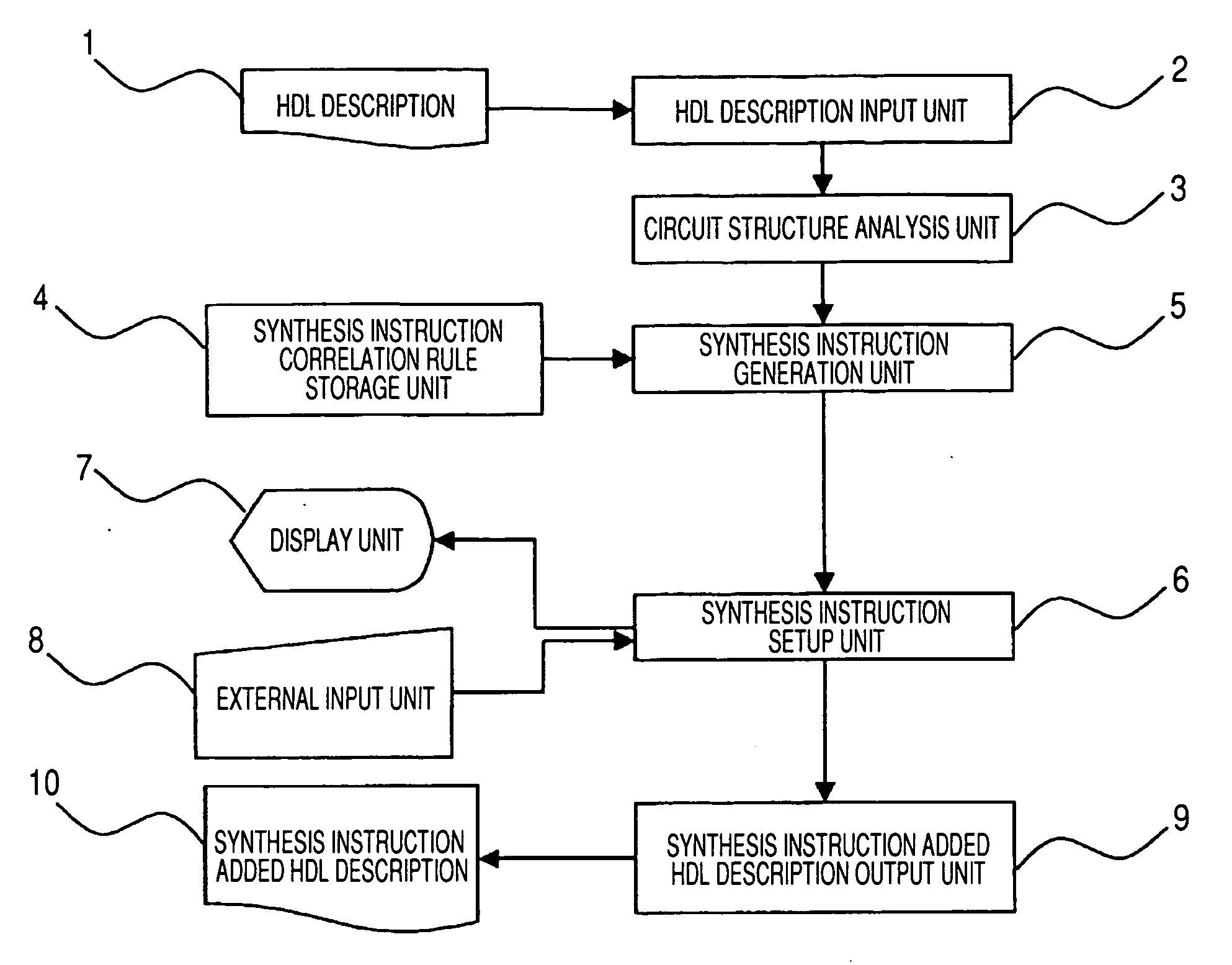
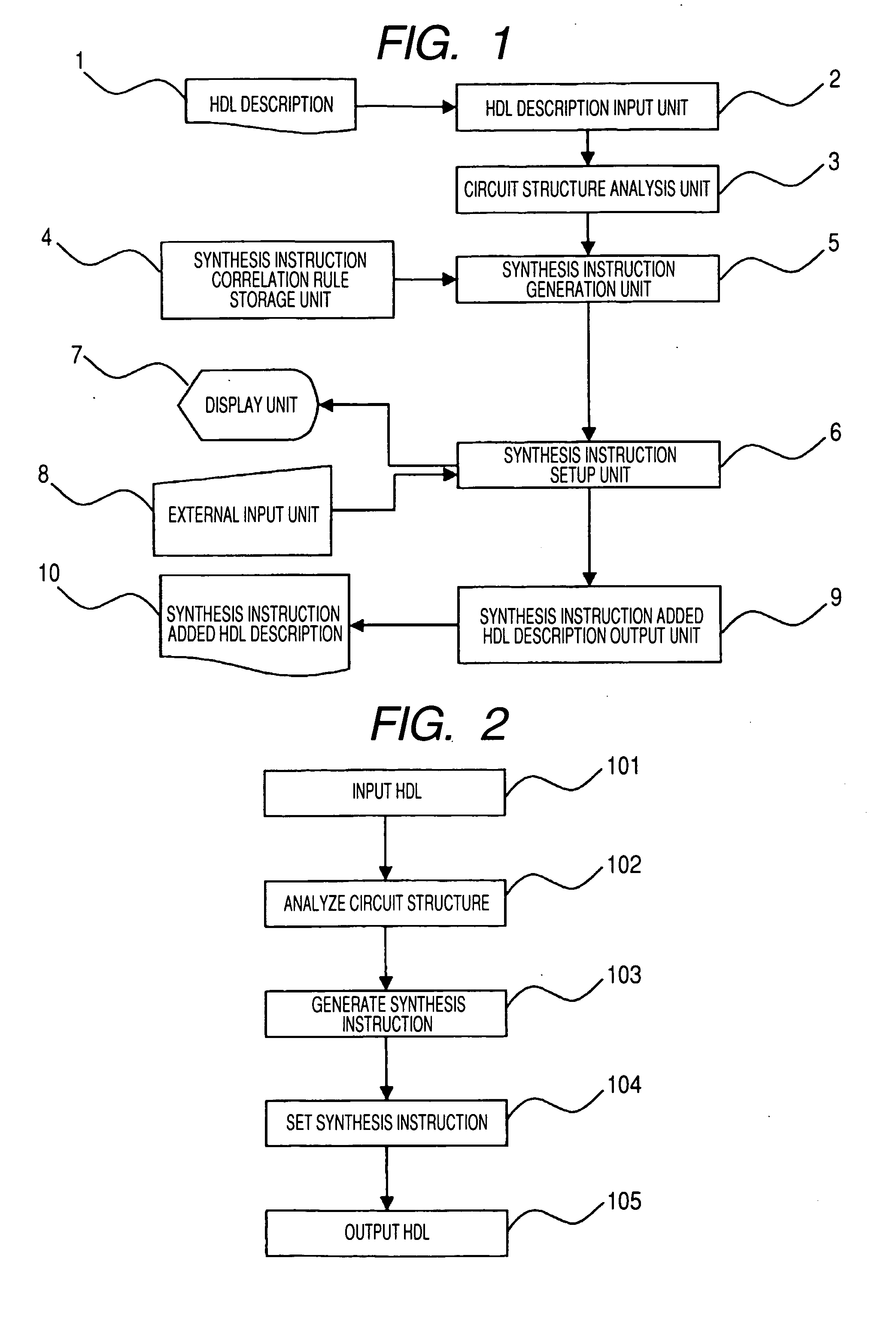
[0097]FIG. 1 is a block diagram showing the configuration of a logic circuit design support apparatus according to a first embodiment of the present invention. As shown in FIG. 1, the logic circuit design support apparatus includes: an HDL description input unit 2, for receiving an HDL description 1, in which circuit information for an RTL is written; a circuit structure analysis unit 3, which analyzes the circuit structure based on the circuit information included in the HDL description that is received; a synthesis instruction generation unit 5, which synthesizes the characteristic of the circuit structure, obtained by the circuit structure analysis unit 3 through an analysis of the circuit structure, and a synthesis instruction correlation rule, obtained from a synthesis instruction correlation rule storage unit 4 in which correlation rules are stored that are correlated with synthesis instruction methods for designated logic synthesis tools; a synthesis instruc...

second embodiment

(Second Embodiment)

[0110]FIG. 7 is a block diagram showing the configuration of a logic circuit design support apparatus according to a second embodiment of the invention. FIG. 8 is a flowchart for the logic circuit design support apparatus and a method therefor according to this embodiment.

[0111] The characteristic of this embodiment is that a circuit structure analysis unit 3 analyzes a circuit structure and thereafter performs a verification function. In FIG. 7, components 1 to 10 are the same as those in FIG. 1 for the first embodiment, and the only difference is that a function verification unit 11 is provided.

[0112] In FIG. 8, the processes at steps 101 to 102 and at steps 103 to 105 are performed in the same manner as they are in FIG. 2 for the first embodiment.

[0113] The process performed by the function verification unit 11 at step 111 will now be described.

[0114] A conventional, formal verification technique is employed as a function verification method, and the follow...

third embodiment

(Third Embodiment)

[0120]FIG. 9 is a block diagram showing the configuration of a logic circuit design support apparatus according to a third embodiment of the present invention, and FIG. 10 is a flowchart for the logic circuit design support apparatus, and a method therefor, according to this embodiment. The characteristic of this embodiment is that an instruction for synthesizing HDL and IP, i.e., a script 12, is entered by a synthesis instruction input unit 13, and a synthesis instruction in the script 12 is allocated to a portion in an HDL description 1 by a synthesis instruction allocation unit 14.

[0121] In FIG. 9, the synthesis instruction input unit 13 receives the script 12, which is for the execution of logic synthesis for the HDL description 1, and the synthesis instruction allocation unit 14 allocates a synthesis instruction, in the script 12, for the portion in the HDL description 1.

[0122] While referring to FIG. 10, the operation of the logic circuit design support app...


PUM


Abstract

A circuit structure analysis unit performs structure analysis for logic circuit information, obtained from an HDL description, and acquires analysis results for function parts, such as a register, an operation unit and a multiplexer. A synthesis instruction generation unit compares the analysis results with a synthesis instruction correlation rule, and automatically generates a synthesis instruction to control a logic synthesis method. Finally, an HDL description output unit outputs a synthesis instruction added HDL description, wherein a synthesis instruction is inserted into the original HDL description. When the synthesis instruction added HDL description is employed in the logic synthesis, starting at the top hierarchical level, a synthesis instruction for the logic circuit is not required in a synthesis execution script.

Description

BACKGROUND OF THE INVENTION [0001] 1. Field of the Invention [0002] The present invention relates to a logic circuit design support apparatus that employs a hardware description language in the design of a logic circuit, and a logic circuit design support method that employs this apparatus. [0003] 2. Description of the Related Art [0004] Conventionally, for designing a logic circuit, logic synthesis is performed. According to this method, based on design information at a register transfer level (hereinafter referred to as an RTL) in a hardware description language (hereinafter referred to as an HDL), such as VerilogHDL or VHDL, a gate level net list is generated that is optimized, depending on technology mapping, by employing, as objective functions, constraints, such as dimensions, timing and power consumption. [0005] To perform logic synthesis, not only must there be entered constraints, such as dimensions, timing and power consumption, which are objectives for optimization, but a...

Claims


Application Information

Patent Timeline
Patent Type & Authority Applications(United States)
IPC IPC(8): G06F17/50
CPCG06F17/5045G06F30/30
Inventor KABUO, CHIESHIMADA, YOKOHAMAGUCHI, KASUMIISHIMURA, TAKASHIFUJIMURA, KATSUYA
Owner PANASONIC CORP
Why Eureka
Try Eureka