Method for dynamic balancing of a clock tree

a clock tree and dynamic balancing technology, applied in the direction of generating/distributing signals, pulse techniques, instruments, etc., can solve the problems of over-estimation unrealistic, time delay of the clock, change the resistance of the metal wires, etc., and achieve the effect of generating more curren

Inactive Publication Date: 2006-01-12
PRINCETON TECH CORP
View PDF0 Cites 8 Cited by
  • Summary
  • Abstract
  • Description
  • Claims
  • Application Information

AI Technical Summary

Benefits of technology

[0009] It is therefore an object of the present invention to provide a controllable buffer to be inserted in a specific level of a clock tree, and provide a controller for adjusting two clocks with different skew by controlling the PMOS / NMOS arrangements in the controllable buffer so as to generate more current for compensating the time delay of slow clock to a sink.

Problems solved by technology

However, different routing lengths for the clock to be connected to a device and different input capacitance of a specific device make the above assumption unrealistic.
A longer wire has a higher resistance and capacitance, which causes the time delay of the clock.
The above method assumes that the temperature and the voltage are both homogenous across the entire circuit all the time, i.e. the above method deems the tree is in a static state, but actually it is not true for an operating integrated circuit chip.
The temperature differences will cause different mobility of the holes / electrons in the semiconductor device and also change the resistance of the metal wires.
These phenomena also cause the time delay from the clock source 0 to the sinks.
Both the voltage drop and the temperature increasement make the above “balanced” clock tree un-balanced.
In order to take care of all the corner circuits with different temperature and voltage drop, the commercial CAD tools insert too many buffers in a clock tree, which makes the clock balance getting worst, since active devices (for instance: buffers) are effected by the voltage and temperature more than passive device (wire).

Method used


Image

  • Method for dynamic balancing of a clock tree
  • Method for dynamic balancing of a clock tree
  • Method for dynamic balancing of a clock tree

Examples


Embodiment Construction

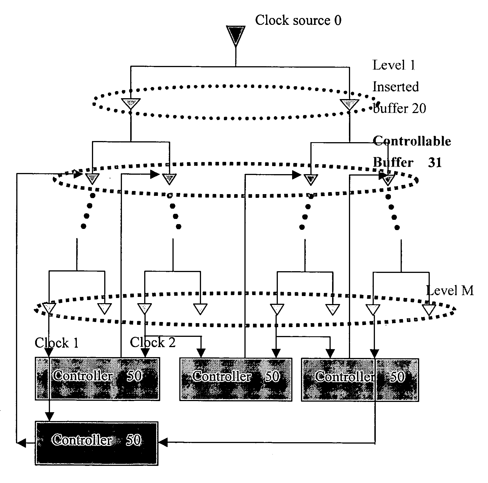
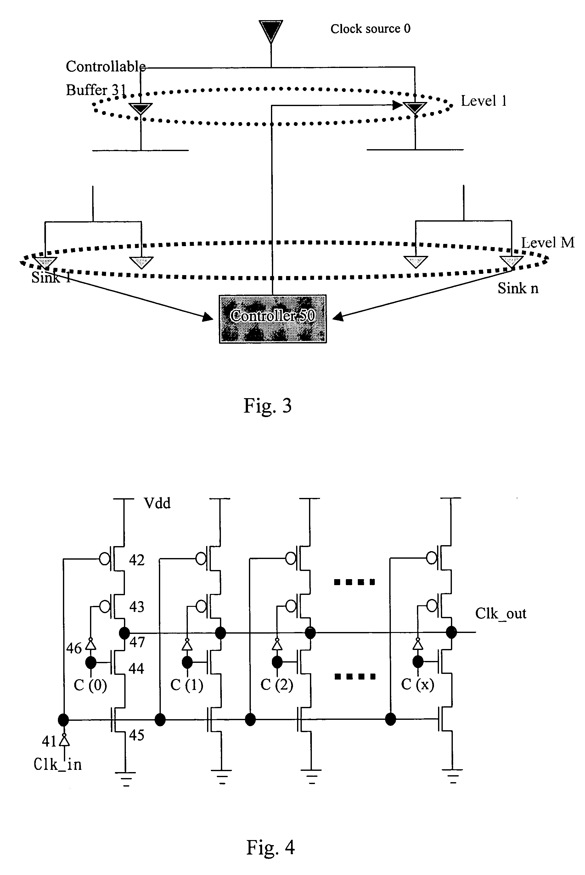
[0016] Referring to the FIG. 3, a clock tree is shown, a controllable buffer 31 is inserted for a spcific level of the tree, and a controller 50 is provided for controlling the controllable buffer 31.

[0017] An example of the controllable buffer 31 is shown in FIG. 4, in which there are several columns of PMOSs and NMOSs combination. Each column has two PMOSs and two NMOSs connected serially as shown. The clock input signal Clk_in is inputted through an inverter 41 to the gates of the top PMOS 42 and the bottom NMOS 45 of each column. Control signals C(0), C(1), C(2), . . . C(x) are inputted to the gates of the central PMOS 43 and NMOS 44 of each colomn respectively. An inverter 46 is inserted between the gates of the central PMOS 43 and NMOS 44 of each colomn respectively.

[0018] As each of the control signals C(0), C(1), C(2), . . . C(x) is “1” (high voltage), a duplicated clock input signal Clk_in will be present as the clock output signal Clk_out at the output terminal 47 of eac...


PUM


Abstract

The present invention provides a method to balance a clock tree dynamically. A controllable buffer is inserted in a specific level of a clock tree, and a controller is provided for adjusting two clocks with different skew by controlling the PMOS / NMOS arrangements in the controllable buffer so as to generate more current for compensating the time delay of slow clock to a sink. This method effectively suppressed the clock skew generated by the voltage drop or the temperature variations in the synchronous logic circuit design.

Description

FIELD OF THE INVENTION [0001] The present invention relates to a method for balancing the clock skew in the synchronous logic circuit design, and more particularly to a special designed circuit for balancing the clock tree to adjust the clock skew in a synchronous logic circuit design. BACKGROUND OF THE INVENTION [0002] In designing a synchronous circuit, it is an assumption that all memory devices use the “same clock”, the clock at each memory device switches at the same time (from high to low or from low to high), and all the rest combinational logic blocks share the same clock interval, so the setup time and hold time related to a clock to change state can be estimated by the memory devices, flip-flop, latch, etc. However, different routing lengths for the clock to be connected to a device and different input capacitance of a specific device make the above assumption unrealistic. [0003] In FIG. 1, it is shown that the clock propagated from the clock source 0 to the sink 1 is fast...

Claims


Application Information

Patent Timeline
Patent Type & Authority Applications(United States)
IPC IPC(8): G06F1/04
CPCG06F1/10
Inventor KAO, DE-YU
Owner PRINCETON TECH CORP
Why Eureka
Try Eureka