One-way clutch and sprag for the one-way clutch

a one-way clutch and sprag technology, which is applied in the direction of clutches, freewheel clutches, couplings, etc., can solve the problems of aggravating the fuel consumption of the one-way clutch used in the automatic transmission, inconvenient meshing of the sprag clutch, and increasing drag, so as to achieve high viscosity

Inactive Publication Date: 2009-02-03
NSK WARNER
View PDF4 Cites 1 Cited by
  • Summary
  • Abstract
  • Description
  • Claims
  • Application Information

AI Technical Summary

Benefits of technology

[0008]Accordingly, it is the object of the present invention to provide a one-way clutch which eliminates the above-noted problems and is greatly improved in meshing during a low temperature, and a sprag for use in the one-way clutch.
[0011]According to the present invention, there is obtained the following effect.
[0012]Since the meshing surface of the sprag which is adjacent to the inner race is formed with a plurality of axially extending grooves, a sufficient meshing property can be secured even during a low temperature at which the viscosity of lubricating oil rises. This is because the grooves formed in the cam surface of the sprag eliminates oil film between the sprag and the inner race which has become high in viscosity during the low temperature, during meshing, and the sprag and the inner race achieve metal-to-metal contact and mesh with each other.

Problems solved by technology

The sprag, however, if the viscosity of lubricating oil becomes high under a very low temperature environment (e.g. −20° C. to −40° C. or lower), does not normally mesh but continuously causes slip when shift is made from idle rotation to meshing, and there may occur the inconvenience that the meshing of a sprag clutch does not function.
H6-313445, minute unevenness is formed on the surface, there is the possibility that lubricating oil of high viscosity collects in the unevenness and becomes oil film to thereby cause continuous slip.
To overcome these problems, it is conceivable to increase a ribbon spring force which applies a load in a meshing direction to the sprag, but an increase in the ribbon spring force may increase the drag during idle rotation, and may cause the aggravation of fuel consumption in a one-way clutch used in an automatic transmission.

Method used


Image

  • One-way clutch and sprag for the one-way clutch
  • One-way clutch and sprag for the one-way clutch
  • One-way clutch and sprag for the one-way clutch

Examples


Embodiment Construction

[0018]The present invention will hereinafter be described in detail with reference to the drawings. The embodiment hereinafter described illustrates the present invention by way of example, and of course does not restrict the present invention. Also, throughout the drawings, like portions are designated by like reference characters.

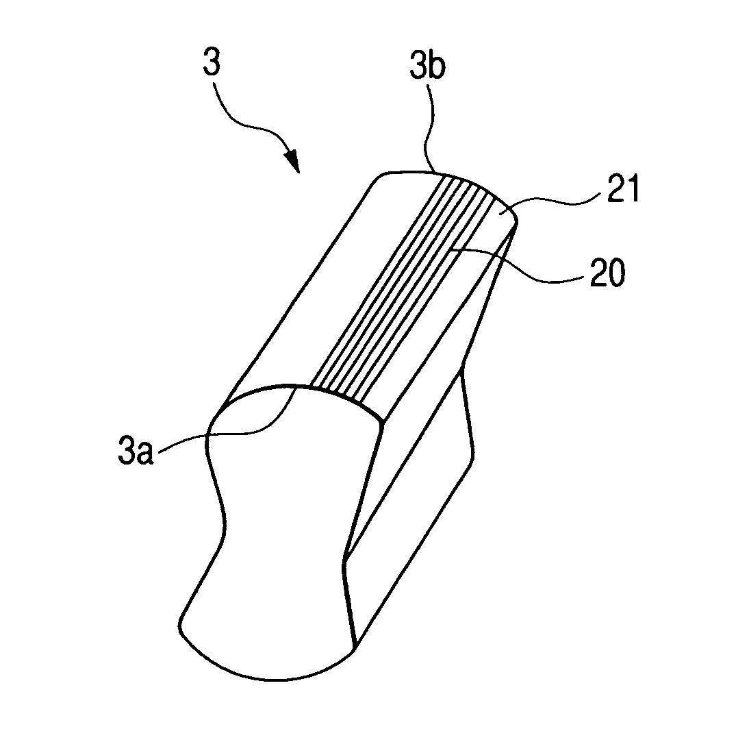
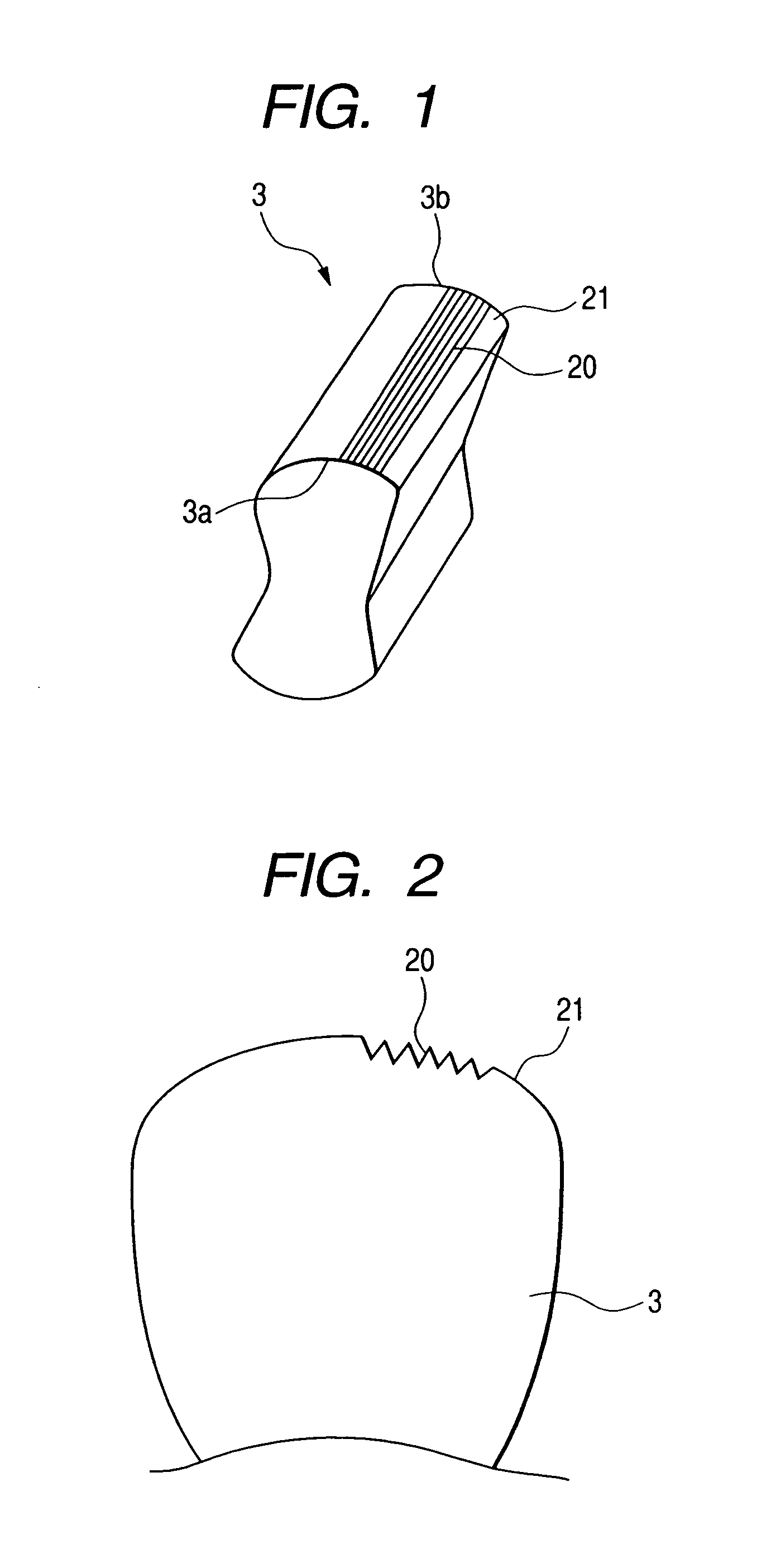
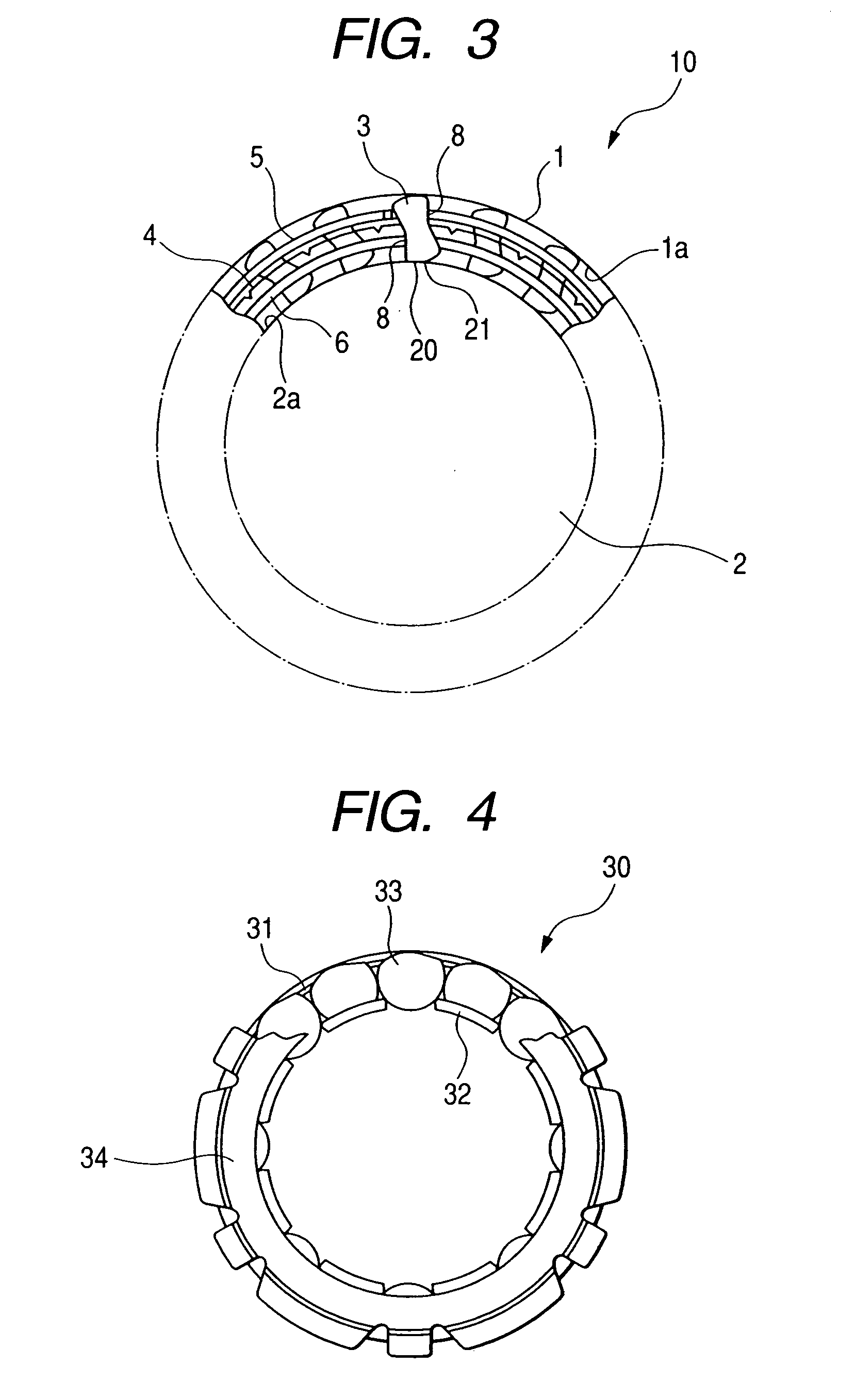
[0019]FIG. 1 is a perspective view of a sprag 3 used in a one-way clutch 10 (FIG. 3) according to an embodiment of the present invention, and FIG. 2 is a fragmentary front view of the sprag 3 of FIG. 1. While here is shown an example in which a gourd-shaped sprag 3 is used as a torque transmitting member, the present invention can also of course be applied to a one-way clutch using other form of sprag.

[0020]As shown in FIG. 1, the sprag 3 has a plurality of axially extending substantially parallel grooves 20 in a cam surface 21. The grooves 20 extend from one axial edge portion 3a to the other edge portion 3b of the sprag 3. That is, the grooves 20 extend...


PUM


Abstract

A one-way clutch comprising an inner race and an outer race radially spaced apart from each other and concentrically disposed for rotation relative to each other, and a spray disposed between the inner race and the outer race for transmitting torque is characterized in that the cam surface of the sprag which contacts with the outer peripheral surface of the inner race is formed with a plurality of axially extending grooves.

Description

BACKGROUND OF THE INVENTION[0001]1. Field of the Invention[0002]This invention relates to a one-way clutch for a torque converter used as a part for torque transmission, back stop, etc., in the driving apparatus of,-for example, an automobile, and more particularly to an improvement in a sprag.[0003]2. Related Background Art[0004]Generally, a one-way clutch comprises an inner race and an outer race radially spaced apart from each other and concentrically disposed for rotation relative to each, and a torque transmitting member disposed between the inner race and the outer race for transmitting torque, and the cam surface of a sprag meshes with the raceway surfaces of the inner and outer races to thereby transmit the torque.[0005]In order to form an oil film, it is preferable that the cam surface of the sprag be as smooth as possible, but in order to give predetermined surface roughness to the cam surface, there is a sprag in which as described in Japanese Patent Application Laid-open...

Claims


Application Information

Patent Timeline
Patent Type & Authority Patents(United States)
IPC IPC(8): F16D41/07
CPCF16D41/07F16D2300/10F16D2041/0603
Inventor MURAMATSU, KAZUHIKOIWANO, AKIRA
Owner NSK WARNER
Why Eureka
Try Eureka