Wind driven generator transmission mechanism adopting chain wheels for speed increasing

A technology for wind turbines and transmission mechanisms, which is applied to wind turbines, engines, machines/engines, etc., can solve problems such as inability to adapt to high-speed transmission, decreased meshing performance with sprockets, and changes in chain pitch, reducing complexity. And, the meshing state is good, and the maintenance is convenient.

Active Publication Date: 2017-02-15
张国欣
View PDF6 Cites 0 Cited by
  • Summary
  • Abstract
  • Description
  • Claims
  • Application Information

AI Technical Summary

Problems solved by technology

But its disadvantage is: during the transmission process of the chain, due to the continuous friction between the chain pin shaft and the chain plate, the chain pitch is easy to change, resulting in the chain becoming longer, and thus the meshing performance with the sprocket is reduced. Therefore, the traditional chain transmission structure cannot Suitable for high speed transmission

Method used


Image

  • Wind driven generator transmission mechanism adopting chain wheels for speed increasing
  • Wind driven generator transmission mechanism adopting chain wheels for speed increasing
  • Wind driven generator transmission mechanism adopting chain wheels for speed increasing

Examples


Embodiment Construction

[0020] The embodiments of the present invention will be described in detail below according to the above-mentioned drawings.

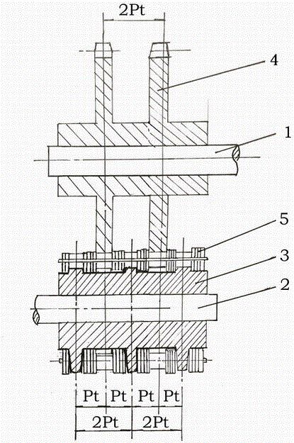
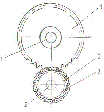
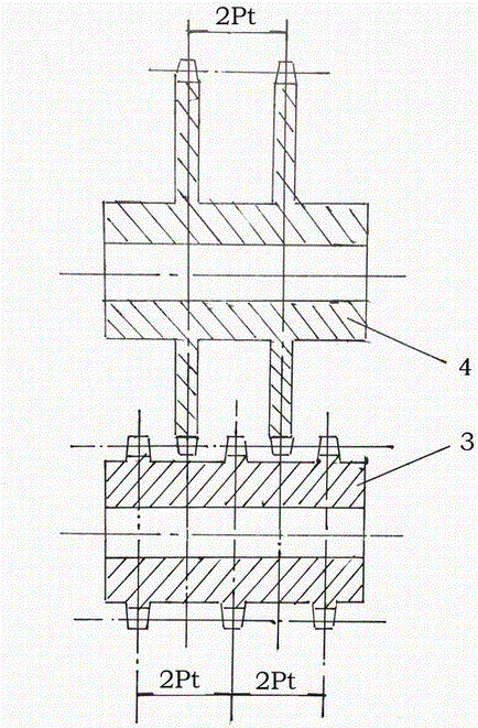
[0021] Such as Figure 1~Figure 3 As shown, 1. high-speed shaft, 2. low-speed shaft, 3. multi-row small sprocket, 4. multi-row large sprocket, 5. multi-row sleeve roller chain.

[0022] A wind power generator transmission mechanism adopting sprocket speed increase, such as figure 1 , figure 2 As shown, it belongs to the field of wind power generators, especially related to the speed-up transmission between the impeller of the wind power generator and the alternator. Output, the low-speed shaft 2 is connected to the impeller and used as power input.

[0023] The high-speed shaft 1 is provided with multiple rows of small sprockets 3 for transmission connection, and the low-speed shaft 2 is provided with multiple rows of large sprockets 4 for transmission connection. The transmission connection has various structural forms, and key connection is usual...


PUM


Abstract

The invention discloses a wind driven generator transmission mechanism adopting chain wheels for speed increasing, and belongs to the field of wind driven generators. The wind driven generator transmission mechanism structurally comprises a high-speed shaft, a low-speed shaft, multi-row small chain wheels, multi-row large chain wheels and the like; multi-row sleeve roller chains are arranged between the multi-row small chain wheels and the multi-row large chain wheels, wheel teeth of the multi-row small chain wheels are surrounded by odd-number-row engaging circumferences of the multi-row sleeve roller chains, the even-number-row sleeve roller chains of the multi-row sleeve roller chains are in the mid-air suspending state on the multi-row small chain wheels, and therefore the multi-row small chain wheels are mounted on the high-speed shaft, the multi-row large chain wheels are mounted on the low-speed shaft, and the speed increasing transmission relation is formed by engaging of the multi-row large chain wheels and the even-number-row chains of the multi-row sleeve roller chains; through the chains, the transmission mechanism with the wind driven generator high-rotating-speed requirement is achieved, the engaging state is good, and on the basis of keeping the use advantages of chain transmission, the beneficial effects of being simple in structural design, capable of reducing complexity of the wind driven generator speed increasing transmission mechanism and the manufacturing cost of a wind driven generator, convenient to maintain and the like are achieved.

Description

technical field [0001] The invention belongs to the field of wind power generators, in particular to a speed-increasing transmission mechanism between the impeller of the wind power generator and the alternator. Background technique [0002] At present, the impeller speed of medium-sized or above wind turbines generally ranges from a dozen rpm to dozens of rpm, while the generator speed is generally 1000 rpm, such as a four-stage AC synchronous generator with a speed of 1500 rpm, which is a common speed. In order to solve the problem of speed difference , the method mainly adopted in the prior art is: adding a gear box between the impeller shaft and the generator shaft for speed-up transmission. The gearbox is a variable speed transmission component widely used in the machinery industry. It has the characteristics of standardization, serialization and a wide variety of specifications, and can meet the requirements of different mechanical transmission functions. Therefore, th...

Claims


Application Information

Patent Timeline
Patent Type & Authority Applications(China)
IPC IPC(8): F16H7/06F16H55/30F03D15/10
CPCF16H7/06F16H55/30Y02P70/50
Inventor 张达汇张燕婷张国欣
Owner 张国欣
Why Eureka
Try Eureka