Screw motor rotor surface dressing device and machining method thereof

A rotor surface, screw motor technology, applied in the direction of coating, etc., can solve the problems of short service life, prone to sparks, wear and so on

Pending Publication Date: 2020-10-09
SINOPEC OILFIELD EQUIP CORP +1
View PDF8 Cites 0 Cited by
  • Summary
  • Abstract
  • Description
  • Claims
  • Application Information

AI Technical Summary

Problems solved by technology

[0007] The main purpose of the present invention is to provide a screw motor rotor surface coating device and processing method to solve the friction phenomenon between the stators, serious wear, short service life, sparks are easy to appear during friction, and it is impossible to transport flammable materials and rotor surface. The rubber dressing is easy to fall and affects the service life of the entire rotor

Method used


Image

  • Screw motor rotor surface dressing device and machining method thereof
  • Screw motor rotor surface dressing device and machining method thereof
  • Screw motor rotor surface dressing device and machining method thereof

Examples


Embodiment 1

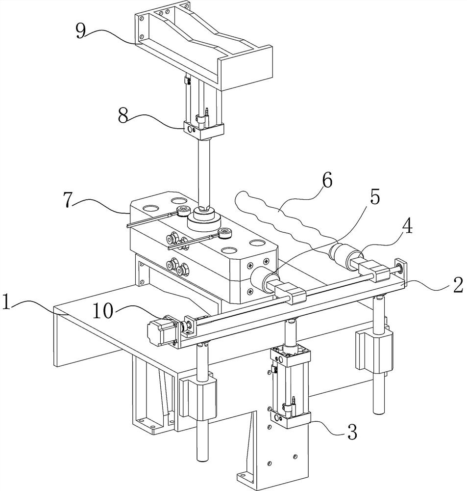
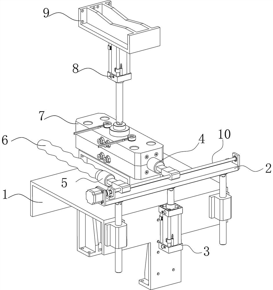
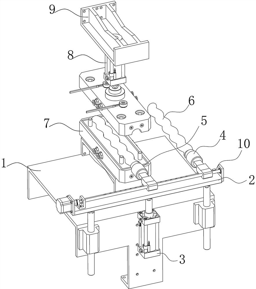
[0046] like Figure 1~11As shown, a screw motor rotor surface dressing device includes a dressing mold 7, the dressing mold 7 includes an upper mold plate 702 and a lower mold plate 703, the upper mold plate 702 and the lower mold plate 703 are provided with a groove body, and the rotor 6 is arranged in the groove body Inside, a hot runner 701 is provided above the upper template 702, and the hot runner 701 communicates with the tank body. With this structure, the upper template 702 and the lower template 703 form the cavity of the dressing, and there is a certain distance between the cavity and the rotor 6. Due to the flow of vulcanized rubber or thermosetting resin, the upper template 702 and the lower template 703 are also provided with exhaust air. The gap of the vent hole and the vent hole should be smaller than the plastic overflow value, and the hot runner 701 is used to transport the vulcanized rubber thermosetting resin.

[0047] The outer surface of the rotor 6 is p...

Embodiment 2

[0061] Further illustrate in conjunction with embodiment 1, as Figure 1~11 As shown, the screw motor rotor 6 uses a tool on the machining center to machine the surface of the screw segment of the rotor 6 into obliquely intersecting kerfs 601, and a bump is formed between the kerf 601 and the kerf 601, forming a plurality of helical lines. The bulge, the bulge is only chamfered.

[0062] Place the rotor 6 for processing the diagonally intersecting knife grooves 601 on the first clamping head 4, the first clamping head 4 is lifted by the first air cylinder 3, and the motor 1004 is driven to drive the first clamping head 4 to slide to the dressing mold 7 between the upper template 702 and the lower template 703.

[0063] The first cylinder 3 is retracted so that the rotor 6 is transported to the inside of the tank body of the lower die plate 703 , and the second cylinder 8 is lifted up to close the upper die plate 702 and the lower die plate 703 .

[0064] The hot runner 701 s...


PUM


Abstract

The invention provides a screw motor rotor surface dressing device and a machining method thereof. The screw motor rotor surface dressing device comprises a dressing mold; the dressing mold comprisesan upper mold plate and a lower mold plate, groove bodies are arranged inside the upper mold plate and the lower mold plate, a rotor is arranged inside the groove bodies, hot runners are arranged above the upper mold plate, and the hot runners are in communication with the groove bodies; the outer surface of the rotor is provided with a plurality of cutter grooves with crossed spiral lines, protruding blocks are formed between the cutter grooves, dressing is injected into the cutter grooves (601) between the protruding blocks through the hot runners, the machining method comprises the steps that crossed spiral groove bodies are machined through a CNC, a plurality of protrusions arranged along the spiral lines are formed, only edges of the protrusions are chamfered, and tops of the protrusions are not chamfered, the machining method is used for increasing the contact area between dressing and the outer surface of the rotor, improving the adhesion strength and prolonging the service lifeof the whole rotor.

Description

technical field [0001] The invention relates to the field of screw motor rotor dressing processing, in particular to a screw motor rotor surface dressing device and a processing method. Background technique [0002] The screw pump is widely used as a feeding device. The screw pump is a positive displacement rotor pump. It relies on the volume change of the sealed cavity formed by the rotor and the stator to inhale and discharge materials. It has stable flow, small pressure pulsation, and self-priming ability. It has the advantages of low noise, high efficiency, long life, reliable operation, etc., and no eddy current is formed when conveying the medium, and it is not sensitive to the viscosity of the medium. It can convey high-viscosity medium. When working, friction will occur between the rotor and the stator, the wear is serious, the service life is short, sparks are prone to occur during friction, and flammable materials cannot be transported. [0003] Existing screw pum...

Claims


Application Information

Patent Timeline
Patent Type & Authority Applications(China)
IPC IPC(8): B29C45/14B29C45/17B29C45/72
CPCB29C45/14221B29C45/14008B29C45/7207
Inventor 信石玉余长柏钱伟强刘平黎爱军李超李盛华胡琼
Owner SINOPEC OILFIELD EQUIP CORP
Why Eureka
Try Eureka