Ophthalmologic observation apparatus

a technology of ophthalmologic observation and apparatus, which is applied in the field of ophthalmologic observation apparatus, can solve the problem of lowering the image quality of the target site obtained

Active Publication Date: 2009-02-03
NIDEK CO LTD
View PDF9 Cites 2 Cited by
  • Summary
  • Abstract
  • Description
  • Claims
  • Application Information

AI Technical Summary

Benefits of technology

[0006]It is a technical object of the present invention to provide an ophthalmologic observation apparatus capable of obtaining a good image of a target site of a eye of an examinee.

Problems solved by technology

However, in practice, a manufacture error exist, which lowers an image quality of the image of the target site obtained.

Method used


Image

  • Ophthalmologic observation apparatus
  • Ophthalmologic observation apparatus
  • Ophthalmologic observation apparatus

Examples


Embodiment Construction

)

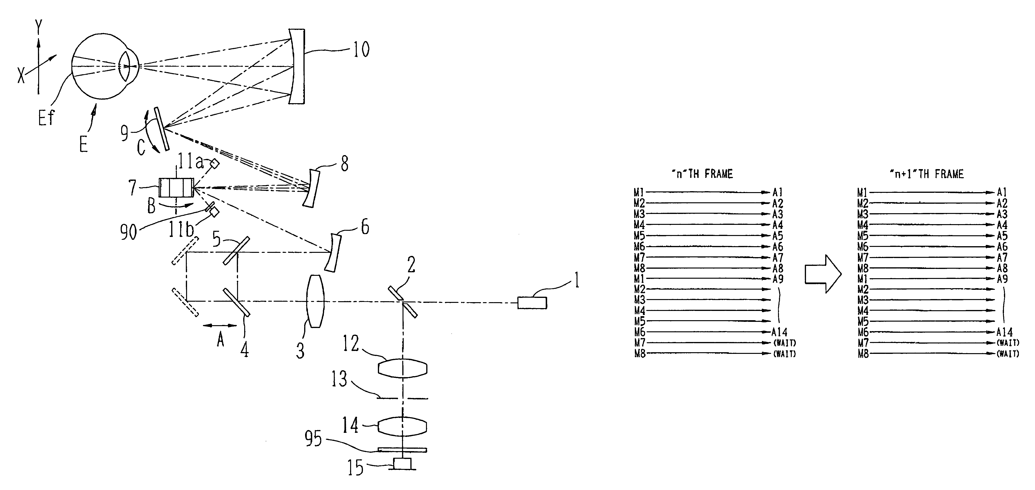
[0027]A preferred embodiment of the present invention will be described with reference to the accompanying drawings. FIG. 1 is a schematic view of an optical system of an ophthalmologic observation apparatus according to an embodiment of the present invention.

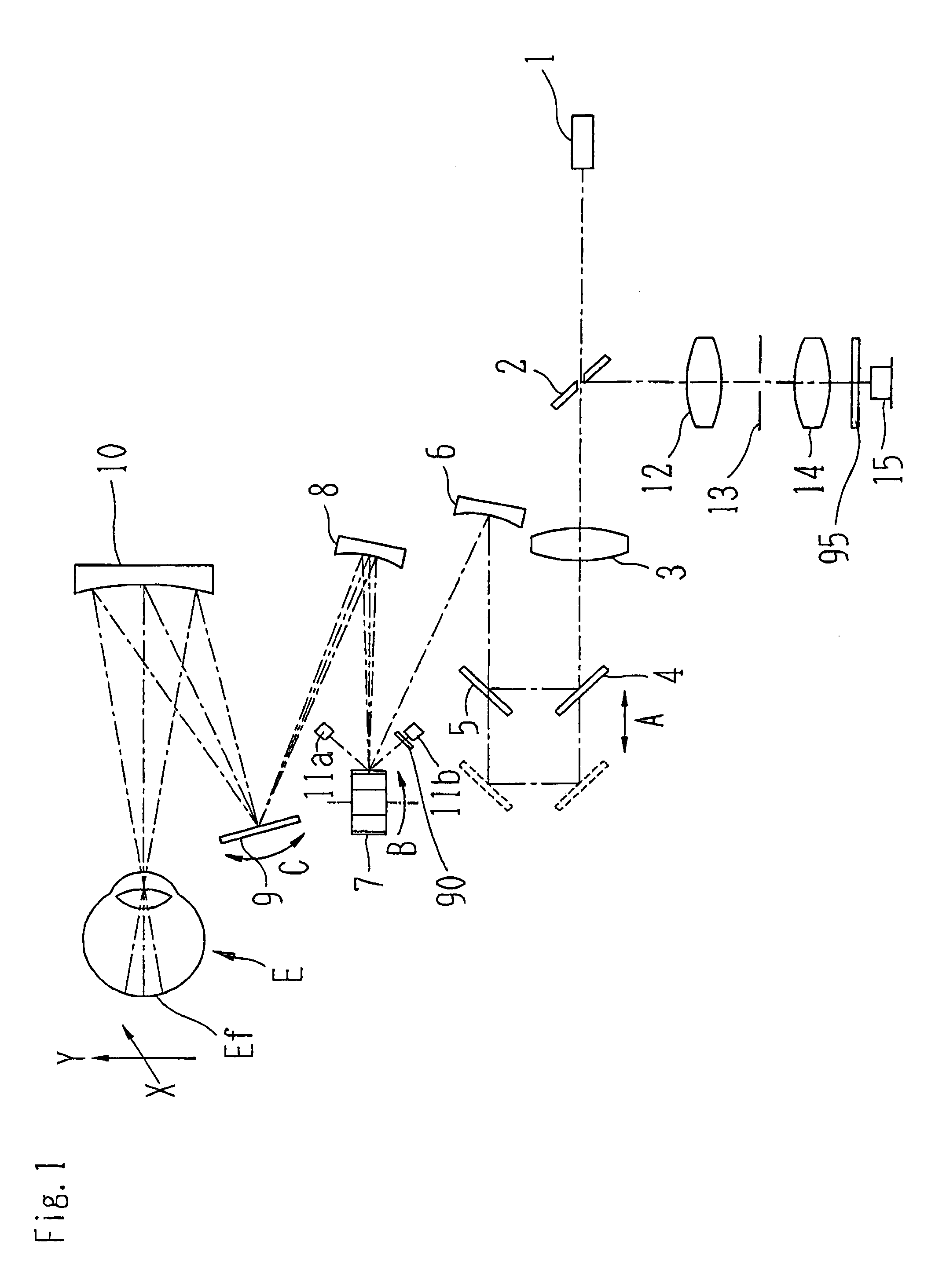
[0028]A laser beam emitted from a laser source 1 passes through a substantially central opening of a hole mirror 2, and then, the laser beam transmits a lens 3. Then, the laser beam is reflected on planer mirrors 4 and 5 and a concave mirror 6, and then, the laser beam is incident to a polygon mirror 7. The laser beam reflected on the polygon mirror 7 is reflected on a concave mirror 8, and then, the laser beam is incident to a galvano mirror 9. The laser beam reflected on the galvano mirror 9 is reflected on a concave mirror 10, and then, the laser beam focuses at a target site of a fundus Ef of an eye E of an examinee. The mirrors 4 and 5 are movably disposed in the direction indicated by an arrow A in FIG. 1, and then, an o...


PUM


Abstract

An ophthalmologic observation apparatus of a confocal laser scanning microscopy system for photographing and observing a target site of an eye of an examinee, includes a controller that, based on a number of image lines of one frame of a motion image to be displayed, a number of reflection faces of a polygon mirror, and a detection result of a photo sensor, controls a galvano mirror and an image forming unit so as to form each image line of each frame of the motion image based on the photo-receiving signals of a laser beam reflected on same reflection face of the polygon mirror.

Description

BACKGROUND OF THE INVENTION[0001](1) Technical Field[0002]The present invention relates to an ophthalmologic observation apparatus of a confocal laser scanning microscopy system, for photographing and observing a target site of an eye of an examinee.[0003](2) Related Art[0004]There is an apparatus for scanning (movably irradiating) a laser beam in a two-dimensional manner to a target site such as a fundus of an examinee, and then, receiving the laser beam reflected at the target site by a photoreceptor element via a pin hole disposed at a position conjugate to the target site, thereby obtaining an image of the target site. In addition, there is an apparatus using a polygon mirror and a galvano mirror in order to scan a laser beam in a two dimensional manner. (Refer to US2005 / 0231685 A1 (Jap. Pat. Appln. No. KOKAI 2005-279121).)[0005]It is preferable that all of the figure tolerance of each reflection faces of the polygon mirror and an angle between the reflection faces be equal to e...

Claims


Application Information

Patent Timeline
Patent Type & Authority Patents(United States)
IPC IPC(8): A61B3/14A61B3/10
CPCA61B3/1025
Inventor AKITA, JUNICHIFUJISHIRO, AKIHIRO
Owner NIDEK CO LTD
Why Eureka
Try Eureka