
Switching voltage regulator comprising a cycle comparator for dynamic voltage scaling

a voltage regulator and dynamic voltage technology, applied in the direction of dc-dc conversion, power conversion systems, instruments, etc., can solve the problems of unfavorable power dissipation, delay in transport and quantization, poor transient response,

Active Publication Date: 2009-02-03
WESTERN DIGITAL TECH INC
View PDF76 Cites 154 Cited by
  • Summary
  • Abstract
  • Description
  • Claims
  • Application Information

AI Technical Summary

Benefits of technology

[0012]In still another embodiment, the switching voltage regulator further comprises a first charging counter operable to time a charge time of the charging element and a second charging counter operable to time a delay pe

Problems solved by technology

The error between the oscillator frequency and a reference frequency represents the gate speed error used as feedback for switching control.
The frequency error is typically generated by computing the average of the oscillator frequency (e.g., using a counter), which introduces transport delay and quantization error into the feedback loop requiring appropriate compensation filtering (e.g., PID filtering).
The compensation filtering typically reduces the bandwidth of the feedback loop which can lead to poor transient response.
This added margin can lead to unnecessary power dissipation, which is of particular concern in portable applications.

Method used


Image

  • Switching voltage regulator comprising a cycle comparator for dynamic voltage scaling
  • Switching voltage regulator comprising a cycle comparator for dynamic voltage scaling
  • Switching voltage regulator comprising a cycle comparator for dynamic voltage scaling

Examples


Embodiment Construction

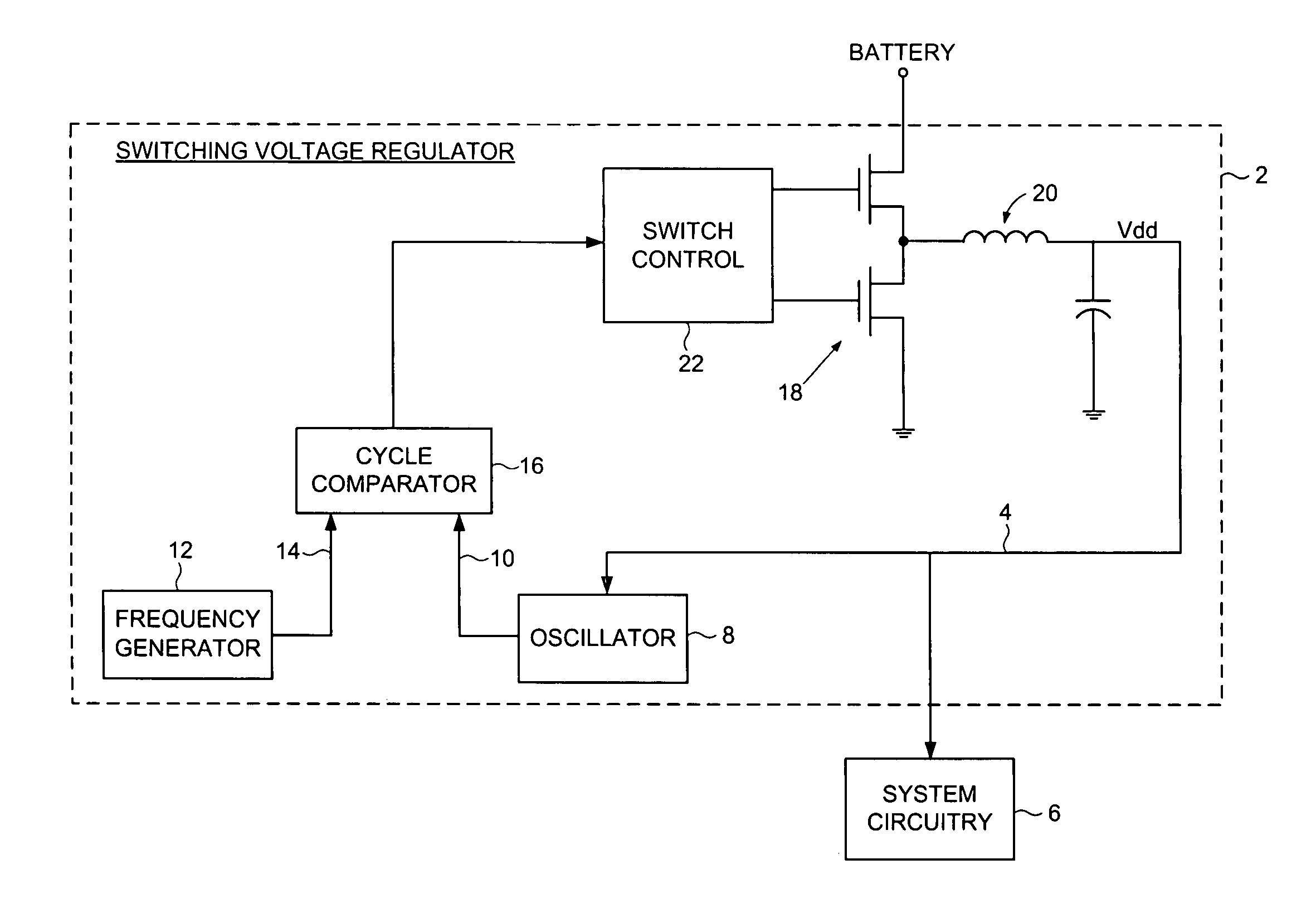
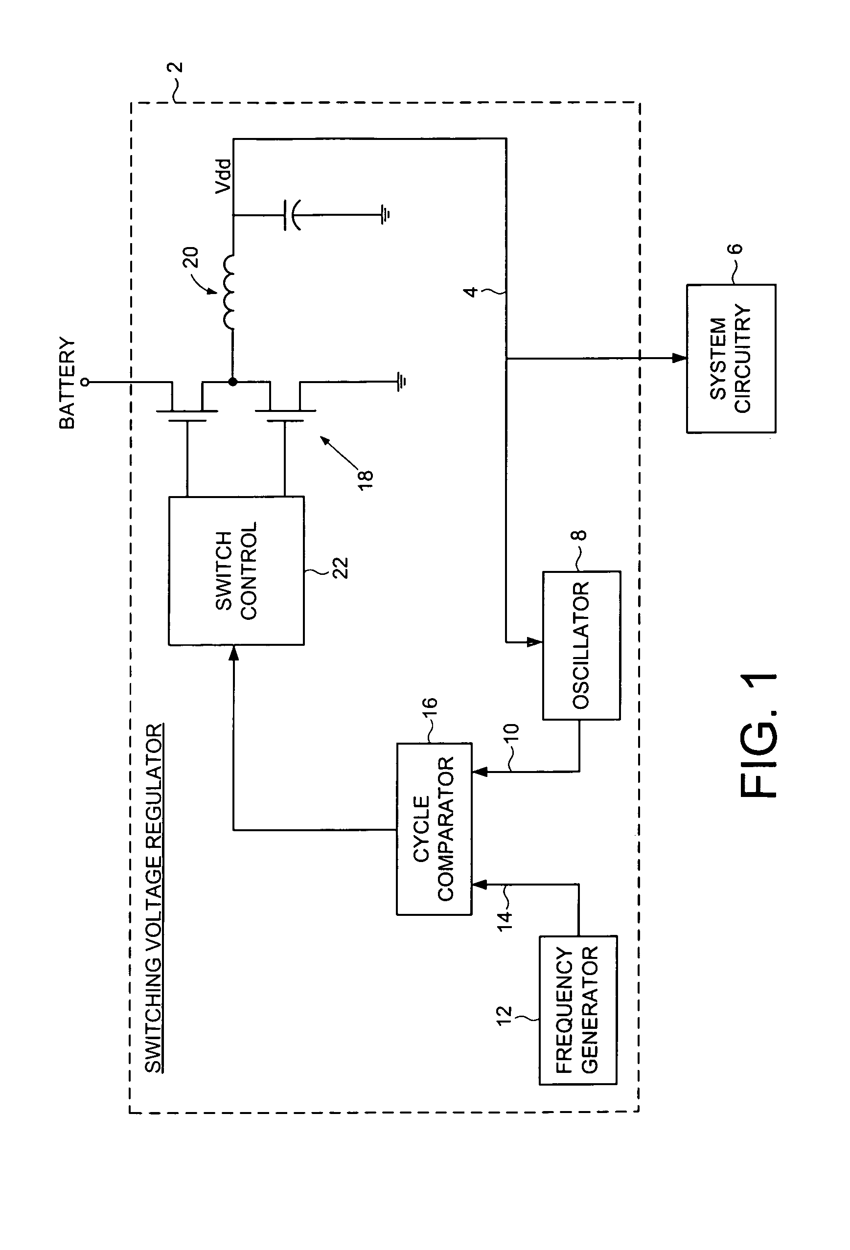
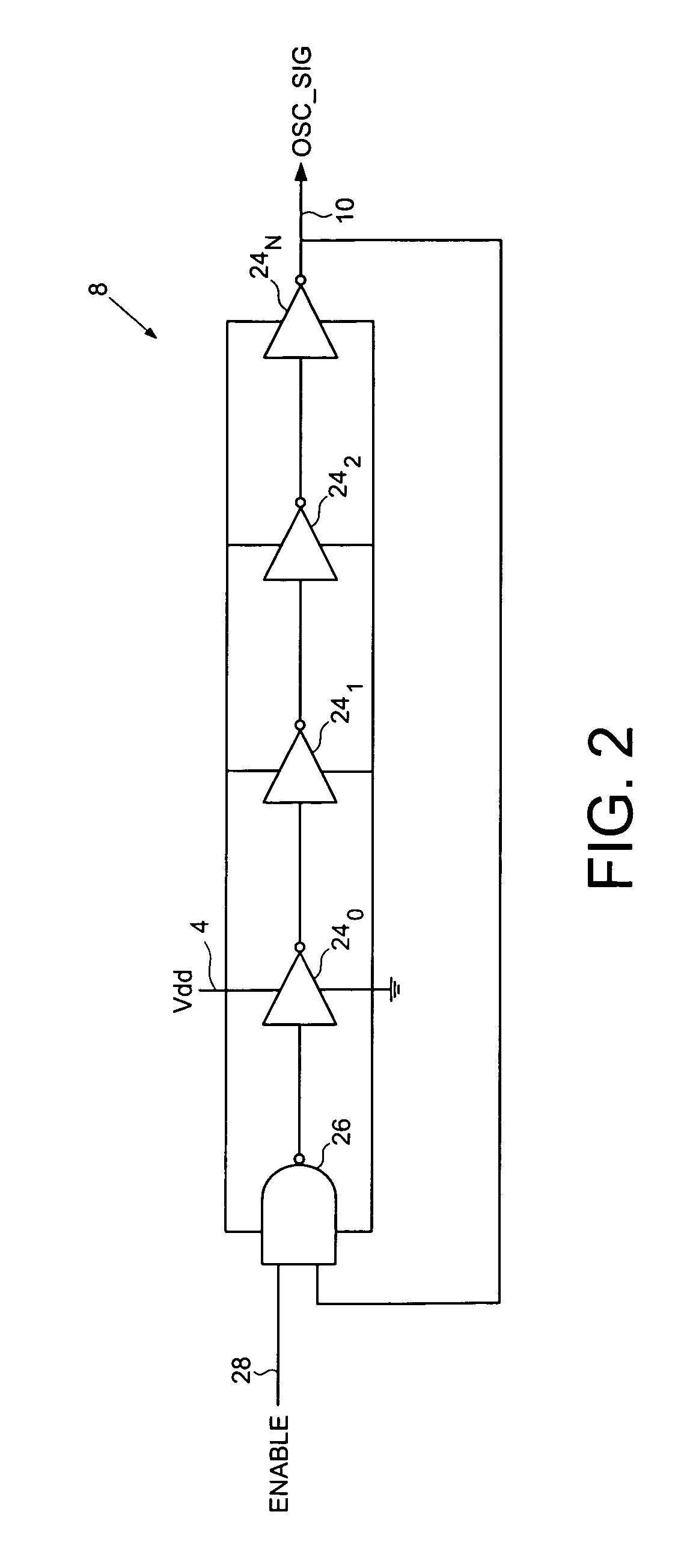
[0018]FIG. 1 shows a switching voltage regulator 2 according to an embodiment of the present invention for regulating a voltage 4 supplied to system circuitry 6. The switching voltage regulator 2 comprises an oscillator 8 operable to generate an oscillator signal 10 representing a gate speed of a reference circuit in the system circuitry 6, and a frequency generator 12 operable to generate a reference signal 14 representing a target gate speed of the reference circuit. A cycle comparator 16 compares at least one cycle of the oscillator signal 10 to at least one cycle of the reference signal 14, and switching circuitry 18 charges a charging element based at least in part on the comparison.

[0019]Any suitable charging element (e.g., an inductor, a capacitor, etc.) may be employed in embodiments of the present invention with any suitable switching voltage regulator configuration. In the embodiment of FIG. 1, a buck mode voltage regulator is shown employing an inductor 20 as the charging...


PUM


Abstract

A switching voltage regulator is disclosed for regulating a voltage supplied to system circuitry. The switching voltage regulator comprises an oscillator operable to generate an oscillator signal representing a gate speed of a reference circuit in the system circuitry, and a frequency generator operable to generate a reference signal representing a target gate speed of the reference circuit. A cycle comparator compares at least one cycle of the oscillator signal to at least one cycle of the reference signal, and switching circuitry charges a charging element based at least on part on the comparison.

Description

BACKGROUND OF THE INVENTION[0001]1. Field of the Invention[0002]The present invention relates to switching voltage regulators. More particularly, the present invention relates to a switching voltage regulator comprising a cycle comparator for dynamic voltage scaling.[0003]2. Description of the Prior Art[0004]Prior art switching voltage regulators (such as discontinuous buck voltage regulators) may implement dynamic voltage scaling in order to optimize power consumption by using critical path gate speed as the feedback for switching control. Various techniques have been disclosed for measuring the critical path gate speed, including the incorporation of a ring oscillator that generates an oscillator signal with a frequency proportional to the gate speed of the critical path circuit (where the gate speed is inversely proportional to the propagation delay of the critical path circuit). The error between the oscillator frequency and a reference frequency represents the gate speed error ...

Claims


Application Information

Patent Timeline
IPC IPC(8): G05F1/40G05F1/56
CPCH02M3/156H02M2001/0025H02M1/0025
Inventor BENNETT, GEORGE J.
Owner WESTERN DIGITAL TECH INC
Learn More