System for attaching trim covers to a flexible substrate

a flexible substrate and trim cover technology, applied in the direction of snap fasteners, buckles, transportation and packaging, etc., can solve the problems of requiring significant skill to create, material will tend to billow or “tents”, and the permanent joint is difficult to repair, so as to prevent excessive flexure of the clip projection legs, prevent single point stress from forming in the legs, and prevent plastically deforming flexur

Inactive Publication Date: 2009-02-10
SMITH LYLE J
View PDF136 Cites 59 Cited by
  • Summary
  • Abstract
  • Description
  • Claims
  • Application Information

AI Technical Summary

Benefits of technology

[0013]This invention overcomes the disadvantages of the prior art by providing a system and method for attaching a fabric trim cover to a flexible / resilient substrate, typically constructed from foam, that includes a plurality of clips that each has a base molded into the substrate. The bases each include a central “keyhole” slot that receives a corresponding key formed on a stem at a bottom of a clip projection. The clip projection defines a cavity for receiving a trim cover bead through a gap formed between a pair of legs that extend from the bottom. The stem has a length that is approximately the thickness of the slot. By passing the key through the slot and rotating the key to a locked position, the clip projection may be removably mounted to the substrate for repair or replacement as needed. The base may be constructed from a material that adheres effectively to the substrate, while the clip projection may be constructed from a material that exhibits high elasticity and wear-resistance.
[0014]In one embodiment, a circular recess is formed on the rear side (facing away from the clip projection) of the base, around the slot. The recess includes a pair of detents that receive opposing ends of the key when the key is rotated relative to the slot. The recess receives a snap-on cap that prevents foam from entering and / or clogging the area around the slot during the molding process. The bases can include one or more end detents for receiving U-shaped clamps formed on the ends of elongated connectors of various lengths. In one embodiment, detents are provided on each of opposing sides of the base and the connectors include a clamp on each opposing end so that chains of bases of varying spacing can be created and disposed within the substrate during the molding process. Alternatively, bases can be attached connectors of various lengths that are fixed at both ends. Similarly, bases can be provided with a fixed connector at one end and a detent at the opposite end. The fixed connectors can define a desired length and include a clamp at the opposing end for locking on to the detent of another base. In this manner, one assembles bases having connectors attached thereto with the desired length to for an appropriately spaced chain of bases.
[0015]To prevent excessive, plastically deforming flexure of the clip projection legs a cradle that includes a pair of reinforced uprights are mounted outwardly from each leg at a predetermined spacing from the respective leg that allows sufficient flexure for a trim cover bead to pass through the barbs at the top of the legs, but that restricts flexure significantly beyond this point. In general, the cradle may / does progressively support the legs so as to prevent single point stresses from forming in the legs. An optional, removable covering cap may be provided to cover the uprights and legs so that these elements remain free of significant foam infiltration during the molding process. Another optional feature is a pair of downwardly projecting anti-rattle tabs that extend at an acute angle from the lower portion of each leg's inner wall. These tabs flex slightly to engage a side of the trim cover bead and / or an associated bead cover piece. The tabs suppress and / or prevent excessive rattle or play for the bead when mounted within the clip.
[0016]In another embodiment the bases can include one or more socket structures having a rectangular cross section and a pair of inwardly offset shoulders for receiving spring-loaded tabs formed on the end of a connector. The structure plugs into the socket, whence the taps expand after compressing during passage into the socket and lock against the inner abutments of the offset shoulders. This structure generally prevents pull-out of the connectors, but otherwise allows the ends of connectors to rotate and flex with respect to bases within a predetermined range of movement.

Problems solved by technology

Otherwise, the fabric will tend to billow or “tent” at these non-planar surface features.
Clearly, this permanent joint is difficult to repair if needed and requires significant skill to create in the first place.
In addition, the use of metal components may be undesirable where the seat includes electrical heating elements due to the metal's predisposition to conduct both heat and electricity.
In molding the clip to the substrate, the clip is exposed to significant heat, which may weaken the clip material.
In addition, because the clip material is adapted to adhere securely to the substrate material, it may not be ideally suited to flexure or cyclic loading.
Likewise, if a clip is damaged during installation or thereafter, then entire foam substrate must generally be discarded as defective.
This is because the clip is permanently mounted to the substrate, and typically cannot be removed and / or replaced without significantly damaging the substrate's surface.
Naturally, a brittle clip composed of a heat-damaged and / or compromised material is more likely to be broken during installation or use.

Method used


Image

  • System for attaching trim covers to a flexible substrate
  • System for attaching trim covers to a flexible substrate
  • System for attaching trim covers to a flexible substrate

Examples


Embodiment Construction

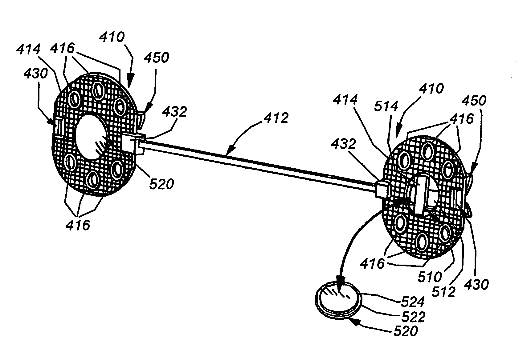
[0037]FIG. 4 details a pair of “chained” or “ganged” clips according to an embodiment of this invention. Each of the clips 410 is an independent unit connected to a flexible, elongated connector 412 that will be described in detail below. In general, clips 410 may be connected in any number using connectors of varying size to create and appropriately spaced chain of connectors for application to a molded resilient substrate (such as an automotive seat bottom or back). Each clip 410 includes a thin-cross-section, enlarged-surface-area base) also termed a “top) 414 that is design to seat within the substrate when hardened. The base is formed from a polymer material that may be particularly suited to provide good adhesion and chemical reaction bonding to the substrate material (typically polyurethane or isocyanate-based foam). Acceptable polymer materials for the base include, but are not limited to, nylon, polyester or any other thermoplastic that has the capability of surviving tempe...


PUM

PropertyMeasurementUnit
diameteraaaaaaaaaa
thicknessaaaaaaaaaa
diameteraaaaaaaaaa

Abstract

This invention provides a system and method for attaching a trim cover to a flexible / resilient substrate, typically constructed from foam, which includes a plurality of clips that each has a base molded into the substrate. The bases each include a central “key-hole” slot that receives a corresponding key formed on a stem at a bottom of a clip projection. The clip projection defines a cavity for receiving a trim cover bead through a gap formed between a pair of legs that extend from the bottom. The stem has a length that is approximately the thickness of the slot. By passing the key through the slot and rotating the key to a locked position, the clip projection may be removably mounted to the substrate for repair or replacement as needed. The base may be constructed from a material that adheres effectively to the substrate, while the clip projection may be constructed from a material that exhibits high elasticity and wear-resistance. A cradle that includes a pair of upright posts that each confront a leg may be provided to progressively support the legs so as to prevent single point stresses from forming in the legs.

Description

BACKGROUND OF THE INVENTION[0001]1. Field of the Invention[0002]This invention relates to trim and upholstery attachment mechanisms, and more particularly to clips for attaching trim and upholstery to foam and other resilient or flexible substrates.[0003]2. Background Information[0004]Modern fabric trim covers (upholstery), such as those used in vehicles, often carefully sculpted and shaped to produce a comfortable and aesthetically pleasing effect. As such, the fabric (typically cloth, vinyl or leather with an appropriate backing material) is secured at many locations along its surface to a resilient or flexible backing that defines the cushioned substrate of the upholstered item (for example, a seat bottom). The substrate is typically constructed from a resilient material. This resilient / flexible material can be synthetic foam (for example polyurethane or isocyanate-based foam) or another cushioning material, such as traditional rubberized horsehair. In general, the close-fitting ...

Claims


Application Information

Patent Timeline
Patent Type & Authority Patents(United States)
IPC IPC(8): B32B3/06A44B18/00A47C31/02A44B99/00
CPCB60N2/5825B60N2/5841B68G7/12Y10T24/2708Y10T24/44769Y10T24/309Y10T24/42B60N2205/30
Inventor SMITH, LYLE J
Owner SMITH LYLE J
Why Eureka
Try Eureka