Sleeping capsule

a capsule and sleeping technology, applied in the field of sleeping capsules, can solve the problems of lack of comfort feeling for a sleeping person, unsuitable for providing thermo-physiologic comfort to the human body, etc., and achieve the effect of preventing a draft from flowing

Inactive Publication Date: 2009-02-10
DAIKIN IND LTD
View PDF12 Cites 13 Cited by
  • Summary
  • Abstract
  • Description
  • Claims
  • Application Information

AI Technical Summary

Benefits of technology

[0018]In accordance with the third and fifth inventions, the flow of air-conditioned air is controlled by means of the wind direction changing plate (6e, 6r, 7r), thereby preventing a draft from flowing towards the sleeping person.
[0020]Accordingly, in accordance with the present invention, it is arranged such that the temperature of conditioned air supplied from the outlet opening (61) and the temperature of conditioned air supplied from the outlet opening (71) are controlled individually, which arrangement makes it possible to form the sleeping compartment (11) capable of providing thermo-physiologic comfort to the human body.
[0021]To sum up, it is possible to keep the sleeping person in a so-called “head cool and feet warm” temperature distribution condition based on the optimal temperature of the human body by individual body regions (in other words, the head is lowest in optimal temperature and the optimal temperature gradually increases from the head towards the feet). As the result of this, it is possible to improve the level of comfort of the sleeping person.
[0022]Furthermore, short circuit regions are formed between the outlet and inlet openings (61, 62) of the head-side inflow / outflow unit (60) and between the outlet and inlet openings (71, 72) of the foot-side inflow / outflow unit (70), thereby ensuring formation of a “head cool and feet warm” temperature distribution.
[0023]In addition, in accordance with the second invention, the arrangement that the inlet opening (62) is located below the outlet opening (61) in the head-side inflow / outflow unit (60) ensures that a short circuit region is definitely formed. More specifically, the conditioned air of the head-side inflow / outflow unit (60), since it is a current of cold wind, is definitely drawn into the lower-situated inlet opening (62).
[0024]Furthermore, the arrangement that the inlet opening (72) is located above the outlet opening (71) in the foot-side inflow / outflow unit (70) ensures that a short circuit region is definitely formed. More specifically, the conditioned air of the foot-side inflow / outflow unit (70), since it is a current of warm wind, is definitely drawn into the upper-situated inlet opening (72).
[0025]Additionally, in accordance with the third invention, since it is arranged such that the wind direction changing plate (6e) is provided in the outlet opening (61, 71), this arrangement definitely prevents a draft from flowing towards the sleeping person.
[0026]Furthermore, in accordance with the fourth invention, the cowl bodies (65, 75) for creating an air-current space which covers the sleeping person's head and an air-current space which covers the sleeping person's feet respectively are provided. As a result of such arrangement, short circuit regions are formed definitely, thereby making it possible to form a “head cool and feet warm” temperature distribution.
[0027]In addition, in accordance with the fifth invention, the cowl bodies (65, 75) are provided with the wind direction changing plates (6r, 7r) respectively, thereby making it possible to prevent a draft from flowing towards the sleeping person and to provide a cooling feeling by a current of air to the sleeping person.

Problems solved by technology

The above-mentioned sleeping capsule, however, suffers from a problem that it is not suitable for providing thermo-physiologic comfort to the human body.
Commonly-used sleeping capsules offer air conditioning control merely capable of keeping the entire sleeping compartment at a set temperature and therefore lack to give a comfort feeling to a sleeping person.

Method used


Image

  • Sleeping capsule
  • Sleeping capsule
  • Sleeping capsule

Examples


embodiment 1

[0049]Hereinafter, a first embodiment of the present invention will be described in detail with reference to the drawings.

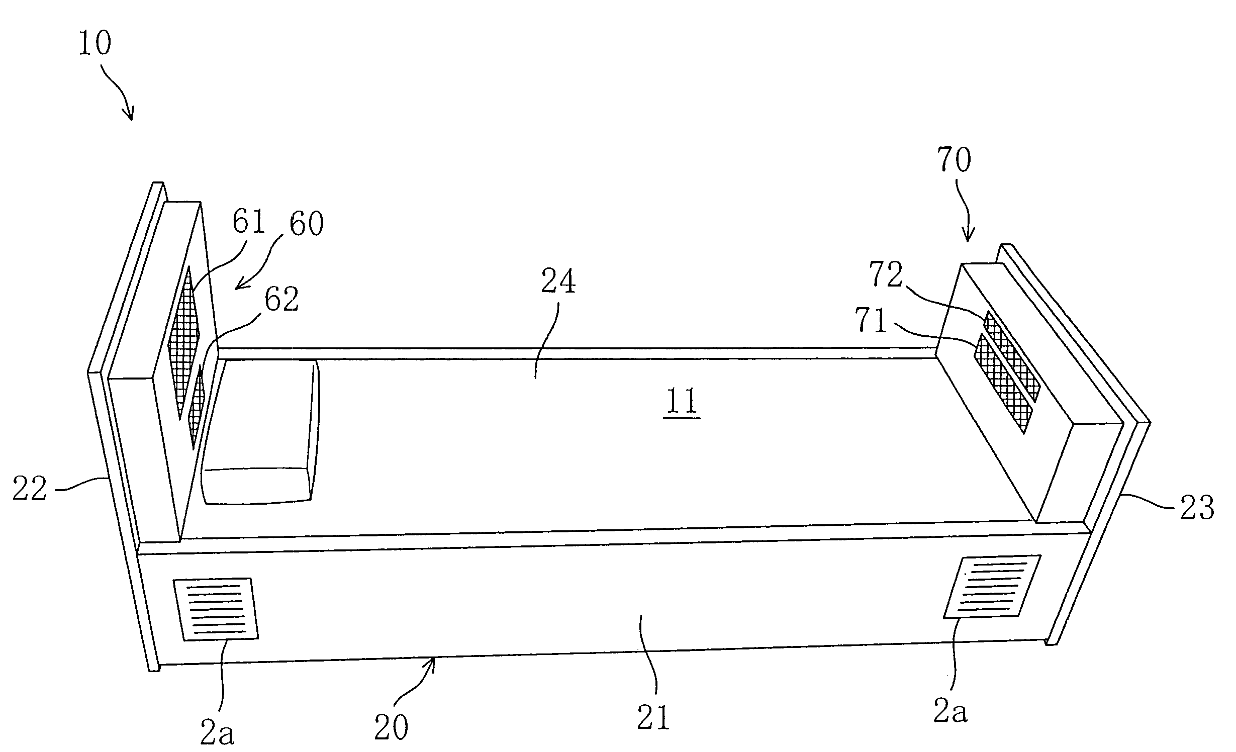
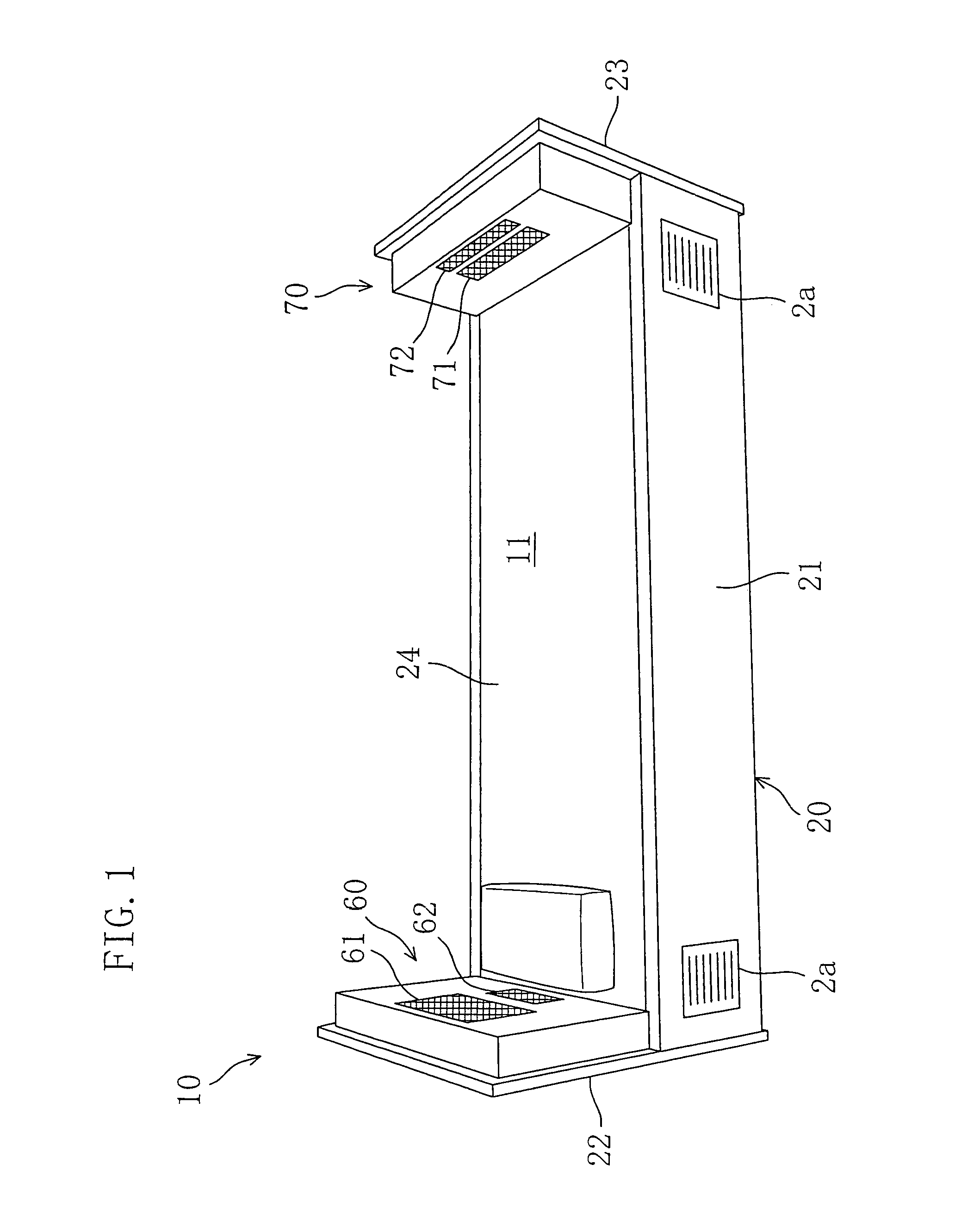
[0050]As shown in FIGS. 1-11, a sleeping capsule (10) of the first embodiment is intended for use by a user who is going to take a nap or the like. The sleeping capsule (10) constitutes a relatively small, enclosed space for a user to sleep in.

[0051]The sleeping capsule (10) is configured such that that the sleeping capsule (10) includes a capsule main body (20) which is provided with two air conditioning systems, i.e., a head-side air conditioning system (3F) and a foot-side air conditioning system (3R).

[0052]The capsule main body (20) is made up of a floor platform (21), a head-side plate (22) arranged at the front of the floor platform (21) (on the side of the head of a sleeping person), a foot-side plate (23) arranged at the rear of the floor platform (21) (on the side of the feet of the sleeping person), and a covering member (40) for covering of both sides ...

embodiment 2

[0095]Hereinafter, a second embodiment of the present invention will be described in detail with reference to the drawings.

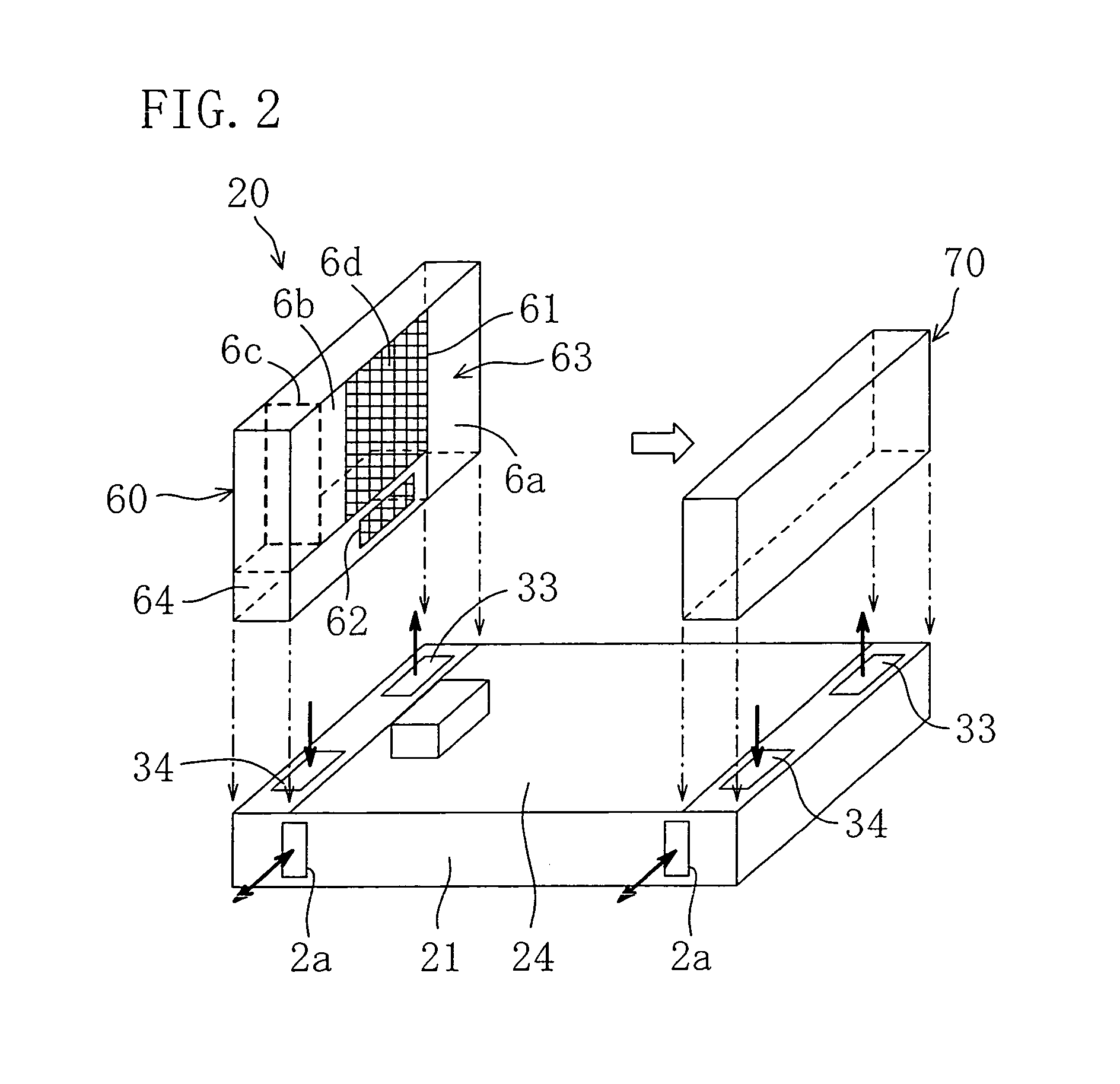
[0096]Referring to FIGS. 12 and 13, there is shown a head-side inflow / outflow unit (60) according to a second embodiment of the present invention. Unlike the head-side inflow / outflow unit (60) of the first embodiment which is shaped like a box which is thin in the front-to-rear direction, the head-side inflow / outflow unit (60) of the second embodiment is shaped like a gate which is thin in the front-to-rear direction.

[0097]More specifically, the head-side inflow / outflow unit (60) of the second embodiment includes a supply passageway (63) which is provided with a longitudinal passageway (6a) and a horizontal passageway (6b). The longitudinal passageway (6a) is formed in a side part of the head-side inflow / outflow unit (60). The longitudinal passageway (6a) has a lower end and an upper end, wherein the former is in communication with the air supply opening (33) wh...

embodiment 3

[0103]Hereinafter, a third embodiment of the present invention will be described in detail with reference to the drawings.

[0104]Unlike the arrangement of the first embodiment that the head- and foot-side inflow / outflow units (60, 70) form respective short circuit regions in front of the outlet and inlet openings (61) and (62) and in front of the outlet and inlet openings (71) and (72), in the present embodiment short circuit regions are formed above the outlet and inlet opening (61, 62) and above the outlet and inlet openings (71) and (72), as shown in FIGS. 14-16.

[0105]The head-side inflow / outflow unit (60) and the foot-side inflow / outflow unit (70) are cowl-shaped so as to cover the head and the feet of a sleeping person.

[0106]More specifically, the head-side inflow / outflow unit (60) is provided with a cowl body (65) made up of a front plate (6m) which becomes the head-side plate (22) of the capsule main body (20), lateral side plates (6n, 6p), and a ceiling plate (6q), wherein th...


PUM


Abstract

A head-side inflow / outflow unit (60) and a foot-side inflow / outflow unit (70), which have a respective outlet opening (61, 71) for providing a supply of conditioned air to a sleeping compartment (11) within a capsule main body (20) and a respective inlet opening (62, 72), associated with the outlet opening (61, 71), for drawing in internal air of the sleeping compartment (11), are provided. The air-conditioning capacity of conditioned air supplied through each of the outlet openings (61, 71) is controlled such that the temperature of conditioned air supplied through the outlet opening (61) of the head-side inflow / outflow unit (60) falls below the temperature of conditioned air supplied through the outlet opening (71) of the foot-side inflow / outflow unit (70). In the head-side inflow / outflow unit (60), the inlet opening (62) is situated below the outlet opening (61), while on the other hand in the foot-side inflow / outflow unit (70) the inlet opening (72) is situated above the outlet opening (71), thereby producing flow of an air current causing a short-circuit between the outlet opening (61, 71) and the inlet opening (62, 72).

Description

TECHNICAL FIELD[0001]The present invention relates generally to a capsule used for sleeping and more particularly concerns measures for the air conditioning of a sleeping compartment of such a sleeping capsule.BACKGROUND ART[0002]Some of previously known sleeping capsules are of the type in which an air outlet opening and an air inlet opening are so formed as to open to a sleeping compartment of a capsule main body, such as the one disclosed in Japanese Utility Model Kokai Publication No. (1992)100545. In such a conventional sleeping capsule, an evaporator is disposed midway along an air passageway by which the inlet opening and the outlet opening are connected together, and air cooled by the evaporator is supplied to the sleeping compartment.[0003]Problems To Be Solved[0004]In a sleeping capsule of the conventional type, indoor air drawn in through a single inlet opening formed at the feet of a sleeping person is cooled as described above. Thereafter, the indoor air thus conditione...

Claims


Application Information

Patent Timeline
Patent Type & Authority Patents(United States)
IPC IPC(8): A47C27/00F24F7/06F25D23/12A47C19/02A47C19/22A47C21/04A61M21/00F24F1/02F24F7/08
CPCA47C19/005A47C19/022A47C19/22A47C21/044A47C29/003A61M21/0094
Inventor MATSUSHIMA, JUNJIMATSUURA, TETSUYA
Owner DAIKIN IND LTD
Why Eureka
Try Eureka