Dust collection unit of vacuum cleaner

a technology of dust collection unit and vacuum cleaner, which is applied in the field of vacuum cleaner dust collection unit and dust collection unit, can solve the problems of difficult filter cleaning, inability to filter micro-scale foreign objects, and inconvenient reuse, so as to improve the accuracy of the product and improve the dust collection efficiency of the dust collection unit. , the effect of improving the reliability of the produ

Inactive Publication Date: 2009-02-10
LG ELECTRONICS INC
View PDF14 Cites 79 Cited by
  • Summary
  • Abstract
  • Description
  • Claims
  • Application Information

AI Technical Summary

Benefits of technology

[0013]An object of the present invention is to provide a dust collecting unit of a vacuum cleaner capable of improving reliability of the product by reducing parts of the dust collecting unit.
[0014]Another object of the present invention is to provide a dust collecting unit of a vacuum cleaner capable of improving accuracy of the product and dust collecting efficiency of the dust collecting unit by manufacturing the inner construction of the product using minimum parts.
[0019]According to the dust collecting unit of the vacuum cleaner, problems of an abnormal product, accuracy deterioration, and manufacturing cost increase can be solved.

Problems solved by technology

However, since it is inconvenient to reuse the filter formed of the porous material and it is difficult to clean the filter, in recent years, a cyclone unit has been widely used.
However, the cyclone unit has a problem in that it cannot filter micro-scale foreign objects.
However, when the porous filter is combined with the cyclone unit, the problem of periodically cleaning the filter still remains.
When the foreign objects are implanted in the porous filter, an airflow rate is reduced, thereby deteriorating the operational efficiency of the vacuum cleaner.
In the meantime, since airflow is switched to several directions to produce a plurality of cyclones in the inside of the dust collecting, the inner structure of the multi-cyclone dust collecting unit is complicated.
However, when the dust collecting unit is manufactured by a process of assembling a plurality of parts, the possibility that defect occurs in the finished product increases as much as that and a labor of an operator increases.

Method used


Image

  • Dust collection unit of vacuum cleaner
  • Dust collection unit of vacuum cleaner
  • Dust collection unit of vacuum cleaner

Examples


Embodiment Construction

[0031]Reference will now be made in detail to the preferred embodiments of the present invention, examples of which are illustrated in the accompanying drawings.

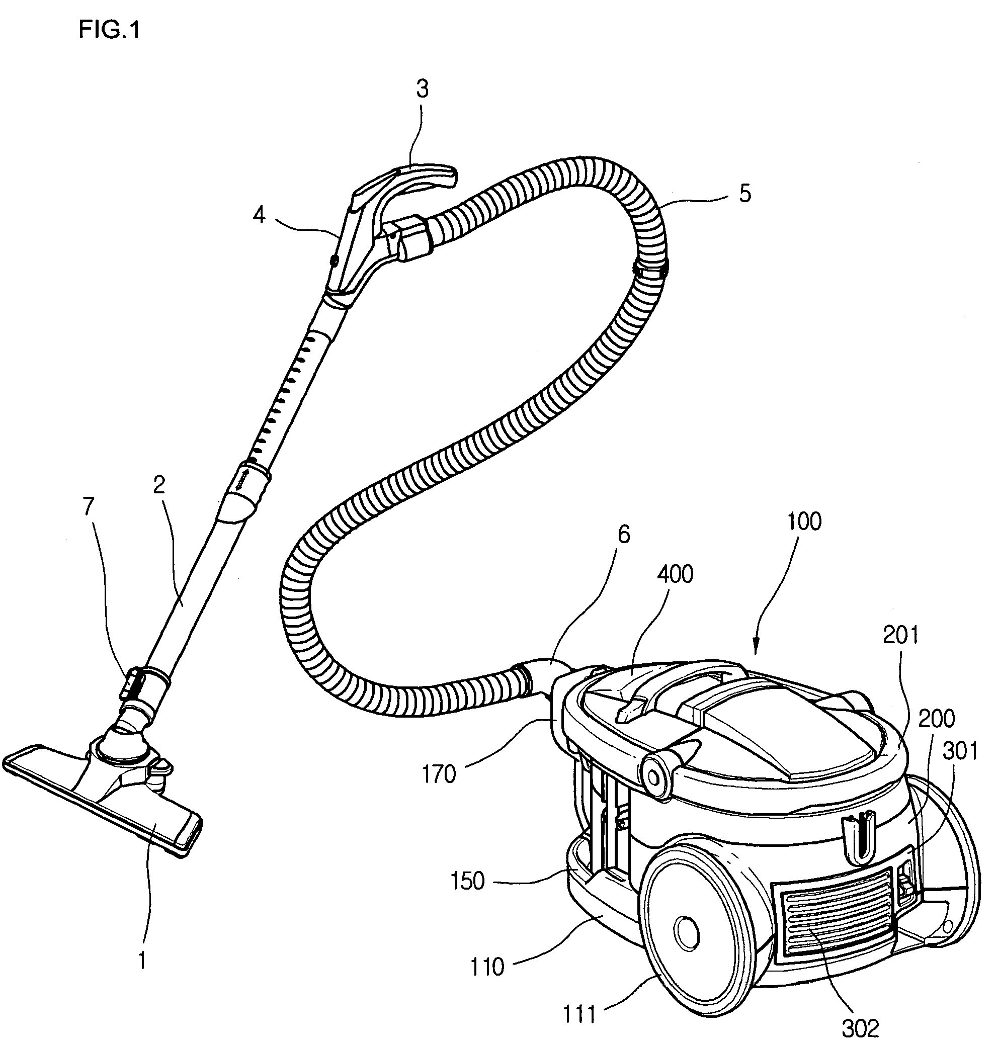
[0032]FIG. 1 shows a vacuum cleaner to which a dust collection unit according to the present invention can be applied.

[0033]Referring to FIG. 1, a vacuum cleaner includes a main body 100 and a suction passage connected to a suction portion of the main body 100. Disposed in the main body 100 are a suction fan (not shown), and a dust collection unit (not shown). Therefore, the sucked air is exhausted out of the main body 100 after foreign objects contained in the sucked air are filtered.

[0034]The suction assembly is provided to suck the air containing the foreign objects when sucking force is generated in the main body 100.

[0035]That is, the suction assembly includes a sucking nozzle body 1 for sucking the air containing the foreign objects using a powerful airflow, an expandable tube 2 extending from the sucking nozzle body 1...


PUM

PropertyMeasurementUnit
thicknessaaaaaaaaaa
distanceaaaaaaaaaa
vacuum pressureaaaaaaaaaa

Abstract

A dust collecting unit of a vacuum cleaner is provided. The dust collecting unit includes: a plurality of storing chambers and a plurality of filtering chambers provided in the inside of a multi-cyclone dust collecting unit. To improve reliability of the product, the storing chambers and the filtering chambers are integrally formed as one body.

Description

BACKGROUND OF THE INVENTION[0001]1. Field of the Invention[0002]The present invention relates to a vacuum cleaner, and more particularly, to a dust collecting unit of a vacuum cleaner that can be manufactured conveniently and simply. Particularly, the present invention relates to a dust collecting unit of a vacuum cleaner such that a collection body in the inside of the dust collecting unit is manufactured in an integral type by a single injection process, so that the manufacturing process is simple and thus manufacturing costs reduce.[0003]2. Description of the Related Art[0004]A vacuum cleaner is used to clean a room or other spaces by sucking air containing foreign objects and filtering the foreign object using vacuum pressure generated therein.[0005]In the meantime, the vacuum cleaner has a dust collecting unit of a predetermined shape mounted within the vacuum cleaner and a filtering device installed in the dust collecting unit, for filtering foreign objects in order to filter ...

Claims


Application Information

Patent Timeline
Patent Type & Authority Patents(United States)
IPC IPC(8): B01D45/12
CPCA47L9/1625A47L9/1641A47L9/1683B04C5/081B04C5/185B04C5/24Y10S55/03A47L9/10
Inventor JEONG, HOI KILHWANG, MAN TAEKIM, YOUNG HOHWANG, JUNG BAEPARK, MIN
Owner LG ELECTRONICS INC
Why Eureka
Try Eureka