High conductance ion source

a high conductance, ion source technology, applied in the field of ion implantation systems, can solve the problems of adversely affecting subsequent implantations using other ion species, affecting the stability of extracted second species, and consuming a lot of time to change the process species, so as to achieve the effect of efficient change of source gases or species used

Inactive Publication Date: 2009-02-10
AXCELIS TECHNOLOGIES
View PDF15 Cites 6 Cited by
  • Summary
  • Abstract
  • Description
  • Claims
  • Application Information

AI Technical Summary

Benefits of technology

[0007]The present invention is directed generally toward an ion source chamber for an ion implantation system, wherein the ion source chamber can be transitioned from one ion source material to another ion source material in an efficient and timely manner. The ion source chamber accomplishes this by providing one or more diffusion apertures associated with the ion source chamber, wherein materials deposited within the ion source chamber from a first ion source material can diffuse through the one or more diffusion apertures when a second ion source material is ionized within the ion source chamber.
[0009]According to another exemplary aspect of the invention, one or more diffusion apertures are further associated with the housing, wherein the one or more diffusion apertures provide a fluid communication between the interior region of the housing and a diffusion region external to the ion source chamber. One or more of the one or more sidewalls, for example, comprise the one or more diffusion apertures therein, wherein a fluid conductance of the first source material and / or second source material from the interior region of the ion source chamber to a region exterior to the ion source chamber is significantly increased, therein providing an efficient and rapid transition between ion source materials.

Problems solved by technology

One drawback to using a single ion implantation system for implanting various species of ions, however, is that such a change in process species can be quite time consuming, since ions from the first process gas are typically deposited onto internal walls of the ionization chamber, and such deposited materials can adversely affect subsequent implantations using other ion species.
Furthermore, the sputtered first species can affect the ionization of the second species, and as a result, the extracted second species will typically require a substantially long amount of time to stabilize.
Long transition periods, however, can adversely affect the ion implantation process.
Also, during the transition period, energy and process species are generally wasted while the system purges the previous species from the ionization chamber.

Method used


Image

  • High conductance ion source
  • High conductance ion source
  • High conductance ion source

Examples


Embodiment Construction

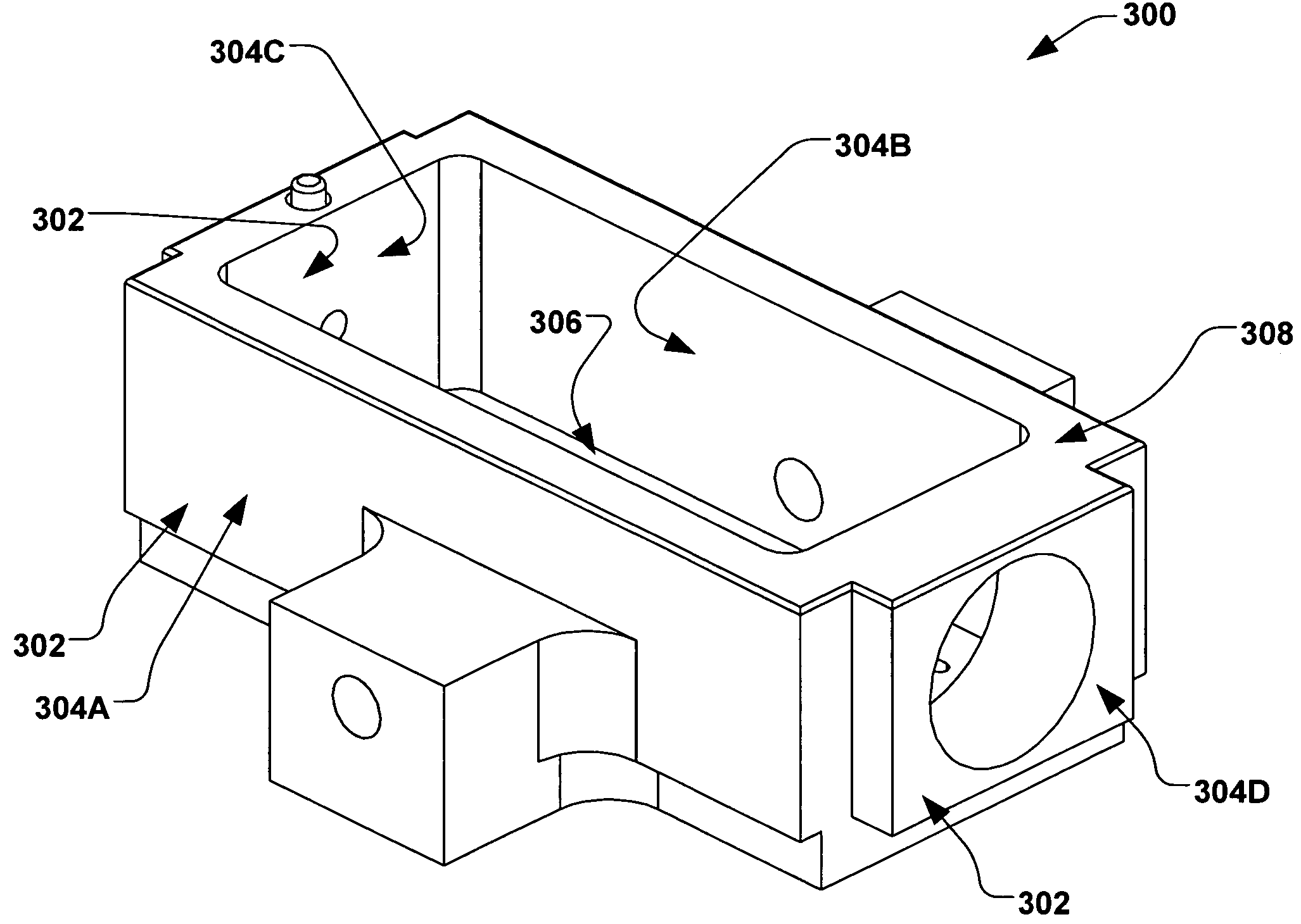
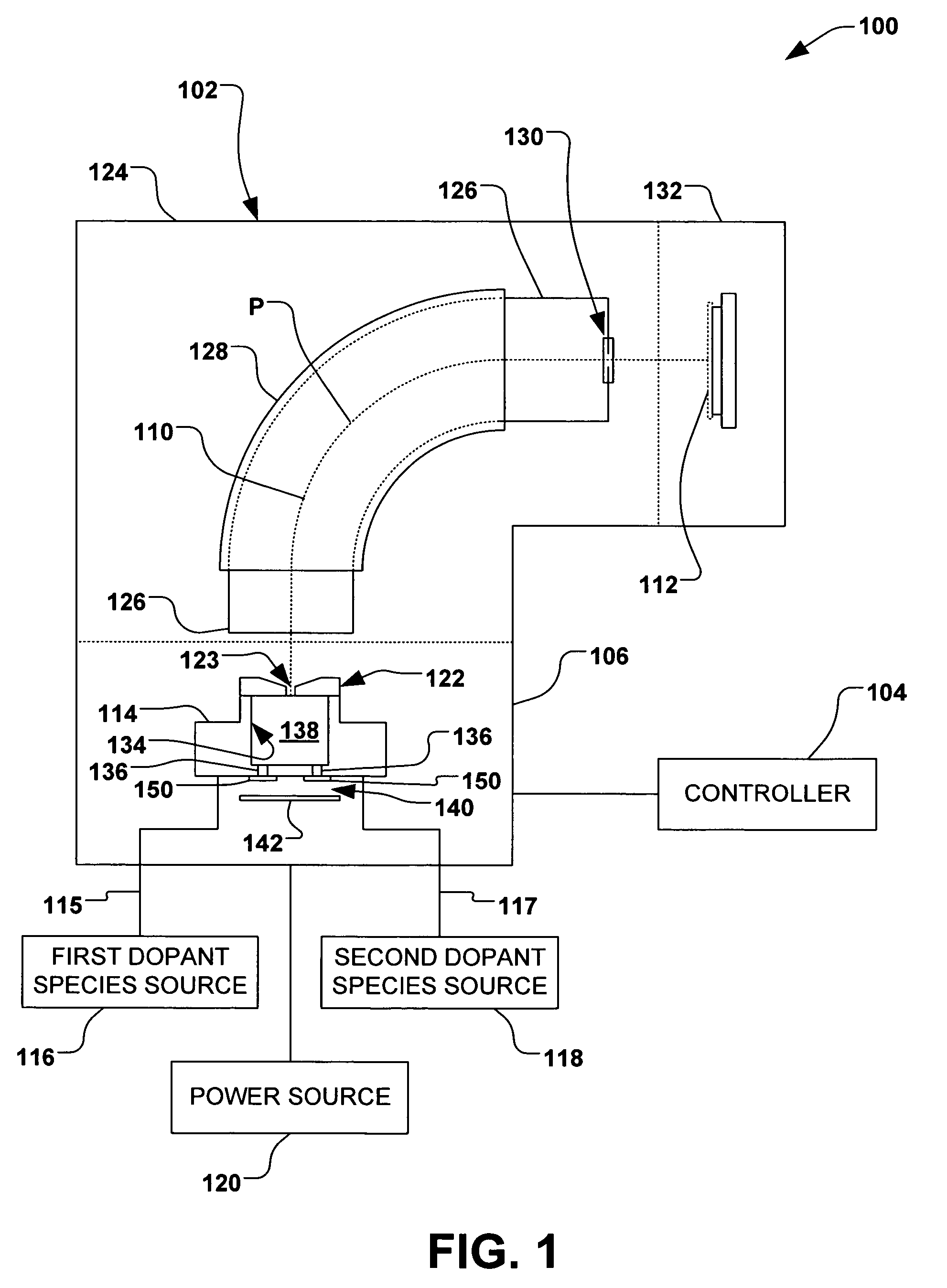
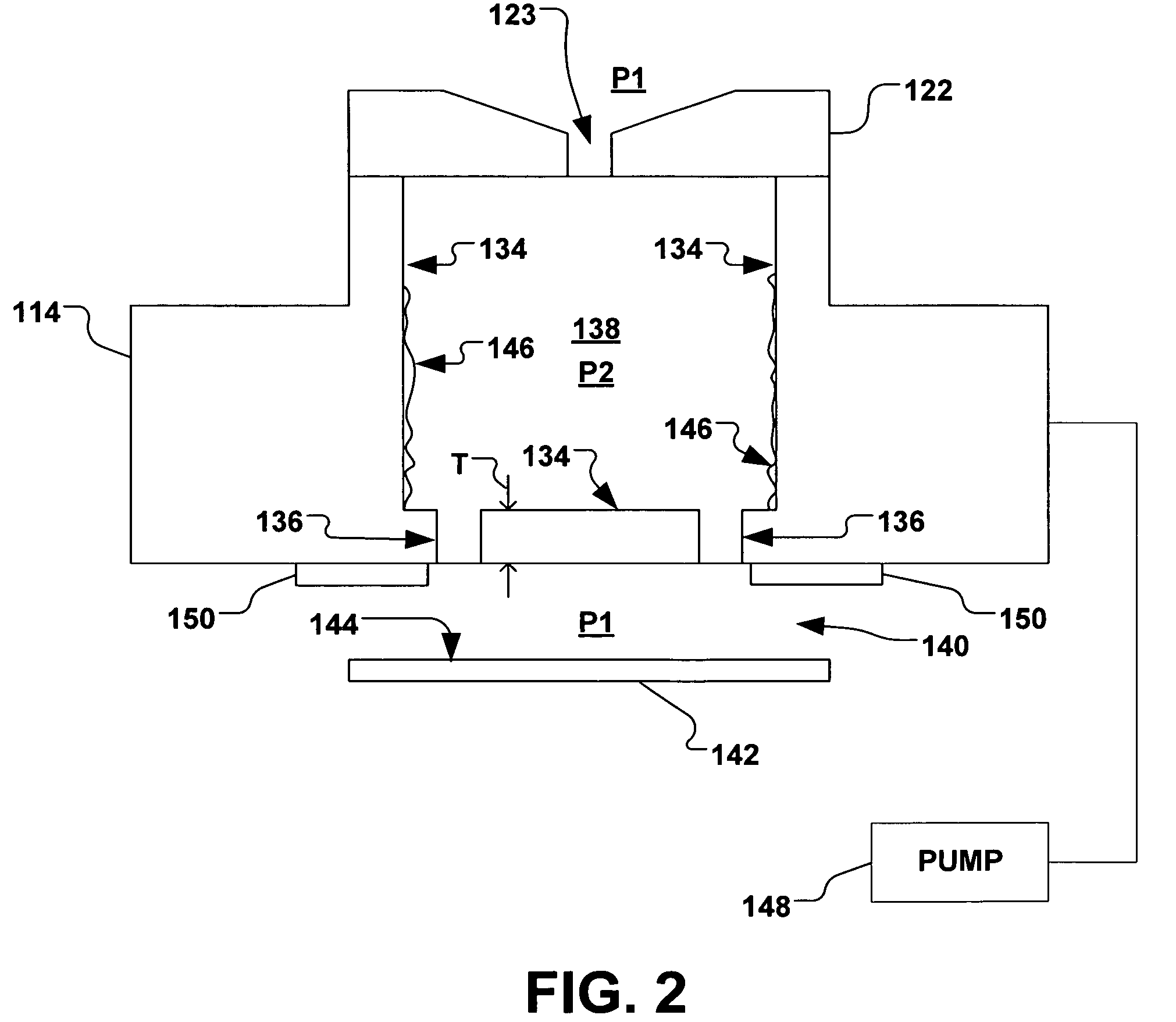
[0018]The present invention is directed generally towards an improved ion source chamber apparatus, ion implantation system, and method for changing ionization species used in ion implantation. More particularly, the apparatus, system, and method provide for an efficient and rapid change of source gases utilized in the ion implantation system. Accordingly, the present invention will now be described with reference to the drawings, wherein like reference numerals are used to refer to like elements throughout. It should be understood that the description of these aspects are merely illustrative and that they should not be taken in a limiting sense. In the following description, for purposes of explanation, numerous specific details are set forth in order to provide a thorough understanding of the present invention. It will be evident to one skilled in the art, however, that the present invention may be practiced without these specific details.

[0019]Referring now to the figures, FIG. 1...


PUM


Abstract

A system, apparatus, and method for changing source gases used for ion implantation is provided. A source chamber has a housing having one or more sidewalls and an extraction plate, wherein the one or more sidewalls and the extraction plate enclose an interior region of the source chamber. One or more inlets provide a fluid communication between one or more ignitable material sources and the interior region. An extraction aperture in the extraction plate provides a fluid communication between the interior region of the source chamber and a beam path region external to the source chamber. One or more diffusion apertures in the one or more sidewalls of the housing further provide a fluid communication between the interior region and a diffusion region external to the ion source chamber, wherein deposited ions are operable to diffuse out of the source chamber through the diffusion apertures.

Description

FIELD OF THE INVENTION[0001]The present invention relates generally to ion implantation systems, and more specifically to a system, apparatus, and method for changing source gases used for ion implantation.BACKGROUND OF THE INVENTION[0002]In the manufacture of semiconductor devices and other products, ion implantation systems are used to impart impurities, known as dopant elements, into semiconductor wafers, display panels, or other work pieces. Typical ion implantation systems or ion implanters treat a work piece with an ion beam in order to produce n- or p-type doped regions, or to form passivation layers in the work piece. When used for doping semiconductors, the ion implantation system injects a selected ion species to produce the desired extrinsic material. Typically, dopant atoms or molecules are ionized and isolated, sometimes accelerated or decelerated, formed into a beam, and implanted into a wafer. The dopant ions physically bombard and enter the surface of the wafer, and ...

Claims


Application Information

Patent Timeline
Patent Type & Authority Patents(United States)
IPC IPC(8): G21K5/10
CPCH01J37/08H01J37/3171
Inventor HUANG, YONGZHANG
Owner AXCELIS TECHNOLOGIES
Why Eureka
Try Eureka