High-frequency power device and method for controlling high-frequency power

a high-frequency power and power device technology, applied in the field to achieve the effects of simplifying the configuration limiting the width of oscillation frequencies, and reducing the cost of high-frequency power devices

Active Publication Date: 2009-02-10
DAIHEN CORP
View PDF3 Cites 23 Cited by
  • Summary
  • Abstract
  • Description
  • Claims
  • Application Information

AI Technical Summary

Benefits of technology

[0024]The present invention was developed in view of the above-described situations. It is an object of an embodiment of the invention to provide a high-frequency power device which does not require any automatic matching unit, and is capable of matching impedance during discharge, achieving a longer service life of the matching unit, decreasing the production costs thereof, and downsizing the unit, and finally is capable of achieving a longer service life of the entire apparatus including the high-frequency power device, decreasing the production costs thereof, and downsizing the entire apparatus, and capable of shortening the matching time (time required to match the impedance) during discharge. Further, it is another object of the embodiment of the invention to provide a high-frequency power device not requiring the discharge detecting unit 57.

Problems solved by technology

However, the variable impedance element of the automatic matching unit 6 described above cannot significantly vary the impedance instantaneously in view of its structure.
As a result, the reflection is increased, power necessary to maintain discharge cannot be supplied to the load, wherein there may be a problem that plasma generated by discharge, etc., disappears.
In Step 3, since the impedance is matched after the discharge is commenced, it is difficult to match the impedance by changing the output frequency due to the above-described situations.
(1) Since the variable impedance element used in the automatic matching unit 6 is provided with a movable portion, the movable portion is subjected to wearing, wherein mechanical longevity is reached. For example, where a variable capacitor is used as the variable impedance element, since the axis of the variable capacitor connected to a motor rotates, the sliding portion between the axis of the variable capacity and a bearing is subjected to wearing, and the wearing reaches mechanical longevity. In particular, since, in the discharge load, the impedance of the load always fluctuates, the variable impedance element also always moves. Accordingly, the wearing degree is made large. Also, since the movement of the variable impedance element differs under the conditions of the load, etc., the period of time to mechanical longevity differs in the respective variable impedance elements. In this connection, as the variable impedance element reaches mechanical longevity, it is necessary that the variable impedance element is replaced or the automatic matching unit 6 is replaced. In this case, it is necessary to carry out replacement work once the production line is stopped. Based on such reasons, it is desired that replacement of the variable impedance element and the automatic matching unit 6 is eliminated. However, in the automatic matching unit 6, since the variable impedance element is employed, there may be cases where the replacement is unavoidable when the components thereof reach mechanical longevity.
(2) In recent years, a demand for lower production costs in the entire apparatus including the high-frequency power device 50 and a demand for downsizing thereof have increased. Since, in the automatic matching unit 6, the variable impedance element is expensive and a motor is required to drive the variable impedance element, the automatic matching unit 6 becomes remarkably expensive, resulting in an increase in the production costs of the entire apparatus including the high-frequency power device 50. In addition, since the structure of the automatic matching unit 6 is complicated and the variable impedance element which is a major part thereof is large-sized, it is difficult to downsize the apparatus.
(3) A demand for further higher speed has been brought about in impedance matching during discharge after the discharge is commenced. However, since the automatic matching unit 6 is conventionally used, the internal variable impedance element cannot instantaneously operate, wherein there may be cases where time of one second through several seconds is required until the impedance is matched.
(4) Further, in the conventional high-frequency power device 50, discharge in the load 5 is detected by using the discharge detecting unit 57. There are various systems of the discharge detecting unit 57, for example, a system for detecting light emission when discharge occurs, a system for detecting a direct current voltage generated in load, etc., are available. However, if the discharge detecting unit 57 is used, there is a problem that the configuration of the high-frequency power device 50 is made complicated. For example, in the system for detecting light emission when discharge occurs, since it is necessary to attach the discharge detecting unit 57 in the vicinity of the load 5, and it is necessary to provide a signal line between the discharge detecting unit 57 and the main body of the high-frequency power device 50, the configuration becomes complicated. In addition, the discharge detecting unit 57 is not inexpensive.

Method used


Image

  • High-frequency power device and method for controlling high-frequency power
  • High-frequency power device and method for controlling high-frequency power
  • High-frequency power device and method for controlling high-frequency power

Examples


embodiment 1

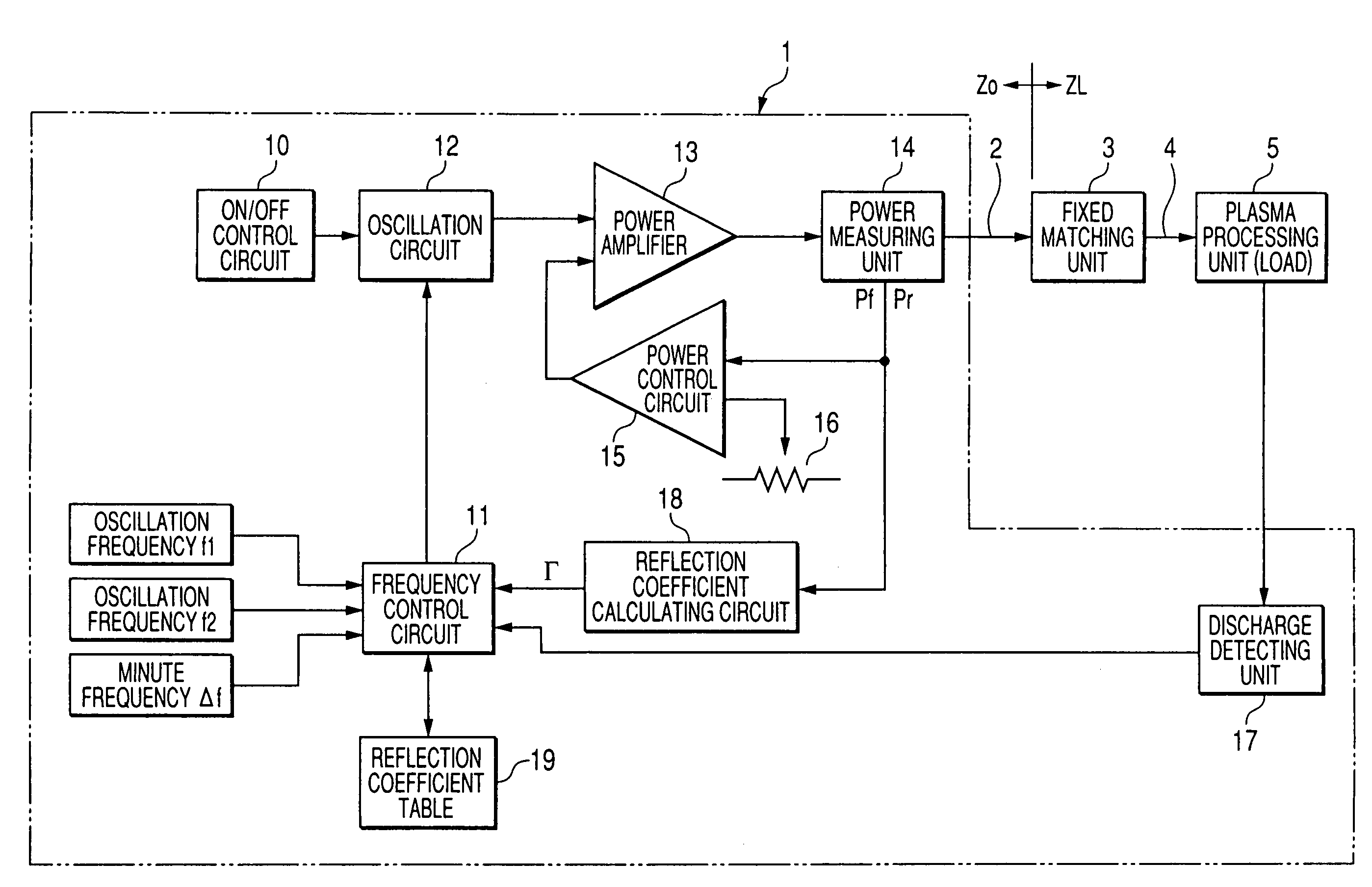
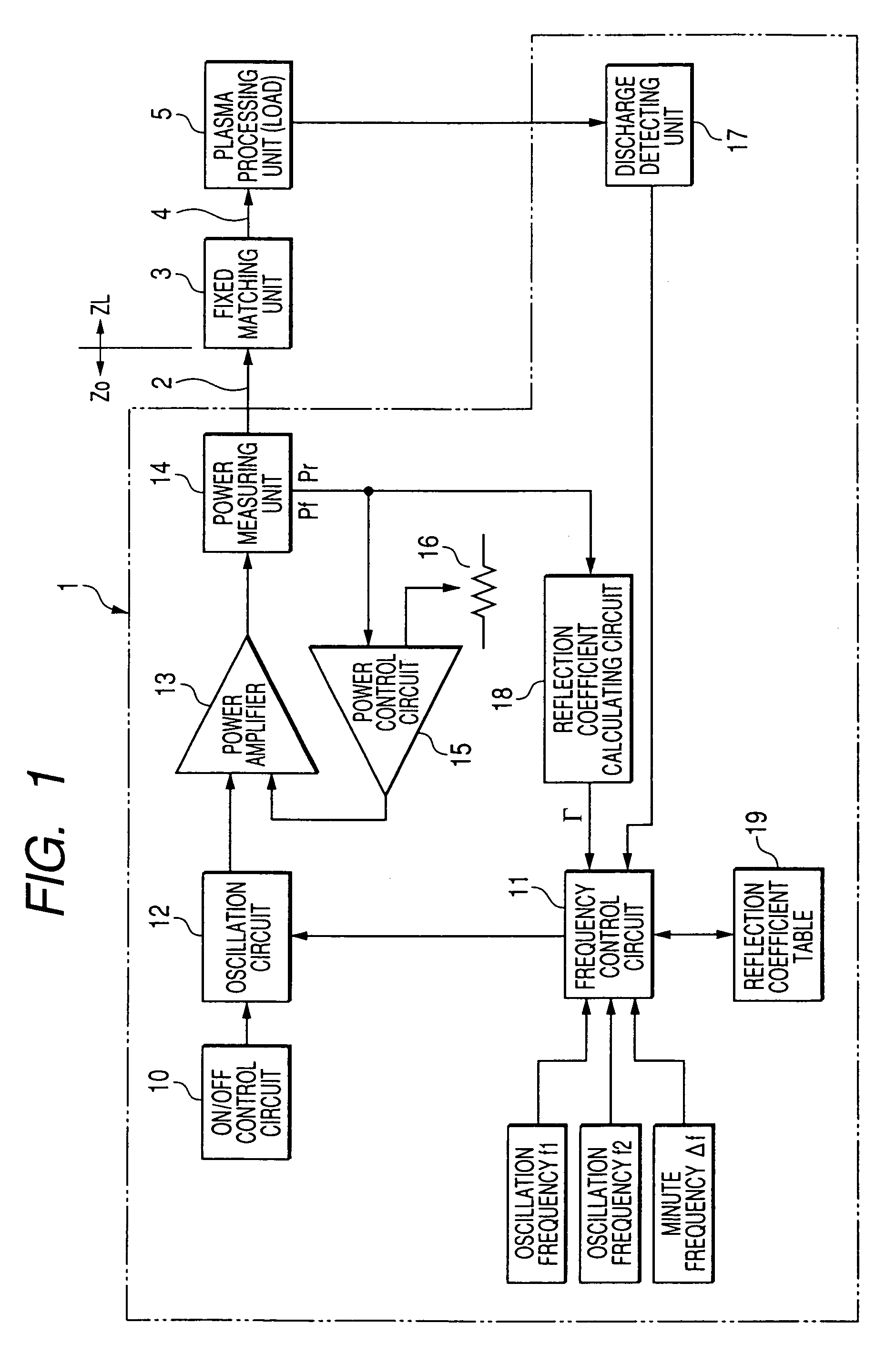
[0066]FIG. 1 is a view showing a configuration of a high-frequency power device 1 according to Embodiment 1 of the invention and a connection between the high-frequency power device 1, a fixed matching unit 3 and a load 5.

[0067]The high-frequency power device 1 amplifies high-frequency signals output from an oscillation circuit 12 by using a power amplifier 13, and supplies generated high-frequency power to a load 5. Also, since the high-frequency power device 1 is a source of generation of high-frequency power to be supplied to a load, it may be merely called a “high-frequency source.” High-frequency power output from the high-frequency power device 1 is supplied to the load 5 via a transmission line 2 composed of a coaxial cable, a fixed matching unit 3, and a load connection portion 4 composed of a shielded copper plate. In addition, generally, this type of high-frequency power device 1 outputs high-frequency power of several hundreds of kHz or more. Also, the power amplifier 13 ...

embodiment 2

[0108]FIG. 6 is a view depicting a configuration of a high-frequency power device 1a according to Embodiment 2 of the invention and depicting a connection between the high-frequency power device 1a, a fixed matching unit 3 and a load 5. The high-frequency power device 1a depicted in FIG. 6 is such that a frequency abnormality judging circuit 20 is added to the high-frequency power device 1 depicted in FIG. 1, the ON / OFF control circuit 10 depicted in FIG. 1 is replaced by an ON / OFF control circuit 10a, and the frequency control circuit 11 depicted therein is also replaced by a frequency control circuit 11a. All others depicted in FIG. 6 are identical to those depicted in FIG. 1, and description thereof is omitted.

[0109]The frequency control circuit 11a has a function of outputting the reference frequency f0 at that time in addition to a function of the frequency control circuit 11 described in FIG. 1.

[0110]The oscillation frequency f2 and a specified oscillation frequency (reference...

embodiment 3

[0119]FIG. 8 is a view depicting a configuration of a high-frequency power device 1b according to Embodiment 3 of the invention and depicting a connection between the high-frequency power device 1b, the fixed matching unit 3 and the load 5. The high-frequency power device 1b depicted in FIG. 8 is such that a timer circuit 22 for measuring the time after the frequency is changed and an initial abnormality judging circuit 23 are added to the high-frequency power device 1a depicted in FIG. 6, the ON / OFF control circuit 10a depicted in FIG. 6 is replaced by an ON / OFF control circuit 10b, and also the frequency control 11a is replaced by a frequency control circuit 11b. The others depicted in FIG. 8 are identical to those depicted in FIG. 6, and description thereof is omitted.

[0120]The high-frequency control circuit 11b has a function of outputting a trigger signal St2 when an instruction is given to change the oscillation frequency f1 to f2, in addition to the function of the frequency ...


PUM


Abstract

A high-frequency power device including: an oscillator; a high-frequency power supplier; a reflection coefficient calculator; a discharge signal output unit; and a frequency controller, wherein the frequency controller: instructs the oscillator to oscillate the oscillation signal at a first oscillation frequency for the period of time while a discharge signal is not in a state showing that the discharge has been commenced or in a state where the discharge is regarded as having been commenced; then instructs the oscillator to change the first oscillation frequency to a second oscillation frequency immediately after the discharge signal changes into the states; and then controls the oscillation frequency so that the absolute value is made small.

Description

BACKGROUND OF THE INVENTION[0001]1. Technical Field of the Invention[0002]The present invention relates to a high-frequency power device for supplying power to a load such as a plasma processing unit, etc., which is employed for applications accompanying discharge such as, for example, plasma etching, plasma CVD, etc.[0003]2. Description of the Related Art[0004]As a high-frequency power device for supplying power to a load accompanying discharge, a high-frequency power device is available, which varies the oscillation frequency of an internal oscillation circuit 52 before and after commencement of discharge in a load.[0005]FIG. 19 is a view depicting a configuration of a conventional high-frequency power device 50 and a connection between a high-frequency power device 50, an automatic matching unit 6, and a load 5. (see, for example, Japanese Published Unexamined Patent Application No. Hei-9-161994)[0006]The high-frequency power device 50 outputs high-frequency power using a power a...

Claims


Application Information

Patent Timeline
Patent Type & Authority Patents(United States)
IPC IPC(8): H03B1/00
CPCH03H7/40H05H1/46
Inventor KOTANI, HIROYUKITAKEI, HIROTAKATANAKA, RYOHEIMATOBA, HIROSHI
Owner DAIHEN CORP
Why Eureka
Try Eureka