Expandable baton for self-protection

a self-protection and baton technology, applied in the field of expandable batons for self-protection, can solve the problems of inconvenient carrying of women, similar problems of batons for self-protection, and inability to expand, etc., to achieve automatic expansion and convenient carrying.

Inactive Publication Date: 2009-02-17
JUNG JAE SUL
View PDF9 Cites 13 Cited by
  • Summary
  • Abstract
  • Description
  • Claims
  • Application Information

AI Technical Summary

Benefits of technology

[0017]An advantage of the present invention is that it provides an expandable baton for self-protection in which a locking piece is mounted inside one end of a cylindrical handle, one end of a telescoping rod is fixed by a locking projection of the locking piece, and the locking piece is caused to elastically move by a switch mounted in the rear side thereof so that multiple telescoping rods supported by a spring are elastically drawn out. Therefore, the expandable baton for self-protection can be conveniently carried in the retracted state at normal times, and can be automatically expanded by a simple switch operation in an emergency.
[0018]Additional aspects and advantages of the present general inventive concept will be set forth in part in the description which follows and, in part, will be obvious from the description, or may be learned by practice of the general inventive concept.
[0019]According to an aspect of the invention, a baton for self-protection is composed of a cylindrical handle, a locking piece, a switch, a first telescoping rod, a second telescoping rod, and a spring. The handle is covered by a grip. The locking piece is coupled to the center portion of a locking piece fixing section inserted into one end of the handle and has a locking projection provided in predetermined positions of both ends thereof. The switch is mounted in the rear side of the locking piece fixing section. The first telescoping rod has a widened portion and tapered portion formed in both ends thereof so as to be telescoped inside the handle. The second telescoping rod is housed in the first telescoping rod, and a step portion of the second telescoping rod at one end thereof is closely coupled to the locking projection of the locking piece. The spring is mounted in the handle so as to elastically support the first and second telescoping rods.
[0020]The handle is composed of a steel rod of which both ends are opened, and the outer circumference of the steel rod is covered by the grip formed of synthetic resin including rubber. Through one opening of the steel rod, the locking piece fixing section having the locking piece inserted therein is mounted.
[0021]The locking piece has a pair of elastically-moving sections formed by cutting the center portion thereof. As the switch engaged with the ends of the elastically-moving sections is pressed, the elastically-moving sections elastically move, so that the end of the second telescoping rod fixed to the locking projections of both sides of the locking piece is released.
[0022]At this time, the second telescoping rod is caused to advance to the front side of the handle by an elastic force of the spring so as to be drawn outside the handle. Simultaneously, a widened portion having the step portion locked to the locking projection of the locking piece comes in surface contact with the tapered portion of the first telescoping rod.

Problems solved by technology

However, the self-protection tools such as a stun gun and gas gun are composed of a complex mechanic device.
Therefore, it is inconvenient for women to carry them because they are heavy in comparison with the size thereof.
The baton for self-protection has a similar problem.
However, the appearance of the baton for self-protection is not beautiful because the hollow tube body of the switching unit is exposed outside.
Further, a plurality of components such as a pressing button, a leaf spring, a fastening pin, a locking member and the like, composing the switching unit, are assembled in a complex manner, thereby increasing a manufacturing cost.
The size of the baton for self-protection inevitably increases because the components of the switching unit are assembled so as to be exposed outside.
Furthermore, as constituting members as well as the switching unit are repeatedly driven, the locking force in the assembled portion is weakened so that a breakdown rate increases.

Method used


Image

  • Expandable baton for self-protection
  • Expandable baton for self-protection
  • Expandable baton for self-protection

Examples


Embodiment Construction

[0031]Reference will now be made in detail to the embodiments of the present general inventive concept, examples of which are illustrated in the accompanying drawings, wherein like reference numerals refer to the like elements throughout. The embodiments are described below in order to explain the present general inventive concept by referring to the figures.

[0032]Hereinafter, the technical construction and operational effect of an expandable baton for self-protection according to the present invention will be described in detail with reference to the accompanying drawings.

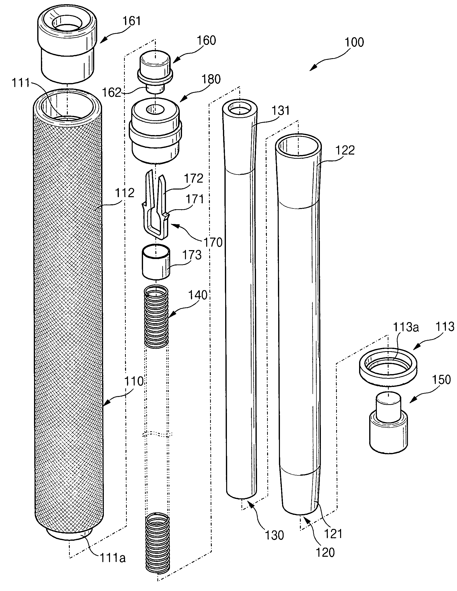
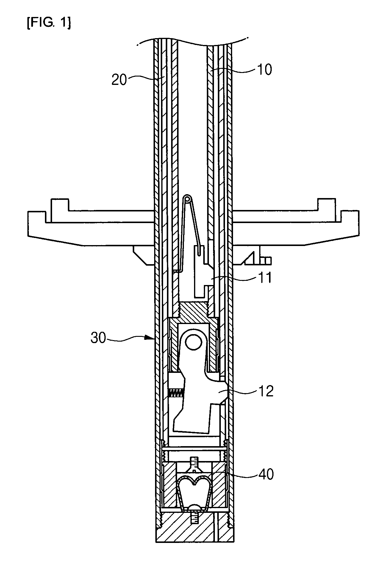
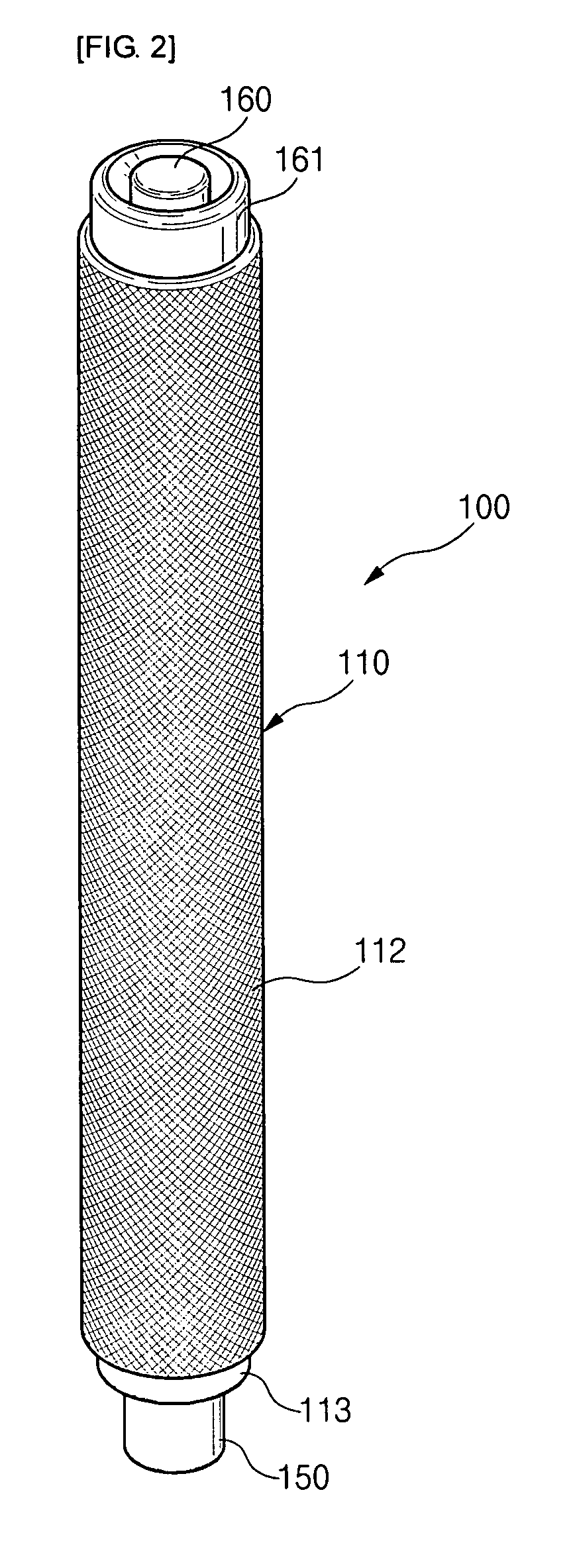
[0033]FIG. 2 is a perspective view of an expandable baton for self-protection of the present invention in the retracted position. FIGS. 3A and 3B are sectional view of the expandable baton for self-protection in the retracted position. FIG. 3A is a sectional view showing a state where a locking piece of a second telescoping rod is locked, and FIG. 3B is a sectional view showing a state where the locking of the loc...


PUM


Abstract

The present invention relates to a baton for self-protection is composed of a cylindrical handle, a locking piece, a switch, a first telescoping rod, a second telescoping rod, and a spring. The handle is covered by a grip. The locking piece is coupled to the center portion of a locking piece fixing section inserted into one end of the handle and has a locking projection provided in predetermined positions of both ends thereof. The switch is mounted in the rear side of the locking piece fixing section. The first telescoping rod has a widened portion and tapered portion formed in both ends thereof so as to be telescoped inside the handle. The second telescoping rod is housed in the first telescoping rod, and a step portion of the second telescoping rod at one end thereof is closely coupled to the locking projection of the locking piece. The spring is mounted in the handle so as to elastically support the first and second telescoping rods.

Description

CROSS-REFERENCE TO RELATED APPLICATIONS[0001]The application claims the benefit of Korea Patent Application No. 2005-0023686 filed with the Korea Intellectual Property Office on Aug. 17, 2005, the disclosure of which is incorporated herein by reference.BACKGROUND OF THE INVENTION[0002]1. Field of the Invention[0003]The present invention relates to an expandable baton for self-protection. In the expandable baton for self-protection, multiple telescoping rods which are elastically coupled to each other inside a cylindrical handle are elastically expanded by a switch operation so that the expandable baton is enlarged. Therefore, the expandable baton can be used for self-protection in an emergency and can be conveniently carried in the retracted state at normal times.[0004]2. Description of the Related Art[0005]Recently, as various violent crimes for unspecific persons increase, various self-protection tools are being developed. Particularly, women buy and use various self-protection to...

Claims


Application Information

Patent Timeline
Patent Type & Authority Patents(United States)
IPC IPC(8): F41B15/02
CPCF41B15/025F41B15/02
Inventor JUNG, JAE SUL
Owner JUNG JAE SUL
Why Eureka
Try Eureka