Weather profile display system and method with uncertainty indication

a weather profile and display system technology, applied in the field of weather radar systems, can solve the problems of affecting the display, the uncertainty amount can still be in the 10,000 foot range, and the conventional weather radar system is only able to produce uncertain hazard assessments for longer ranges

Active Publication Date: 2009-02-17
ROCKWELL COLLINS INC
View PDF87 Cites 74 Cited by
  • Summary
  • Abstract
  • Description
  • Claims
  • Application Information

AI Technical Summary

Problems solved by technology

Heretofore, conventional weather radar systems are only able to produce uncertain hazard assessments for longer ranges.
The uncertainty of those assessments is driven by the variableness of weather, the extreme low level radar returns in environments such as the tops or sides of conductive weather, and the vertical beam width inherent in weather radar systems.
This uncertainty affects the display of hazards in the plan view, range / height displays and the potential panoramic (angle / angle) displays.
Conventional weather radar systems have been able to effectively reduce the 35,000 foot beam width via signal processing techniques, but the amount of uncertainty can still be in the 10,000 foot range.
Since uncertainty decreases with decreasing range to a weather target, hazardous regions above detectable convective cells may be detected later than desired forcing aircrews to make very late non-optimum avoidance maneuvers and may even cause periodic inadvertent thunderstorm penetrations.
An uncertainty of 10,000 feet can also cause periodic unnecessary deviations if regions that have an uncertain risk assessment are found to be not hazardous as range decreases.

Method used


Image

  • Weather profile display system and method with uncertainty indication
  • Weather profile display system and method with uncertainty indication
  • Weather profile display system and method with uncertainty indication

Examples


Embodiment Construction

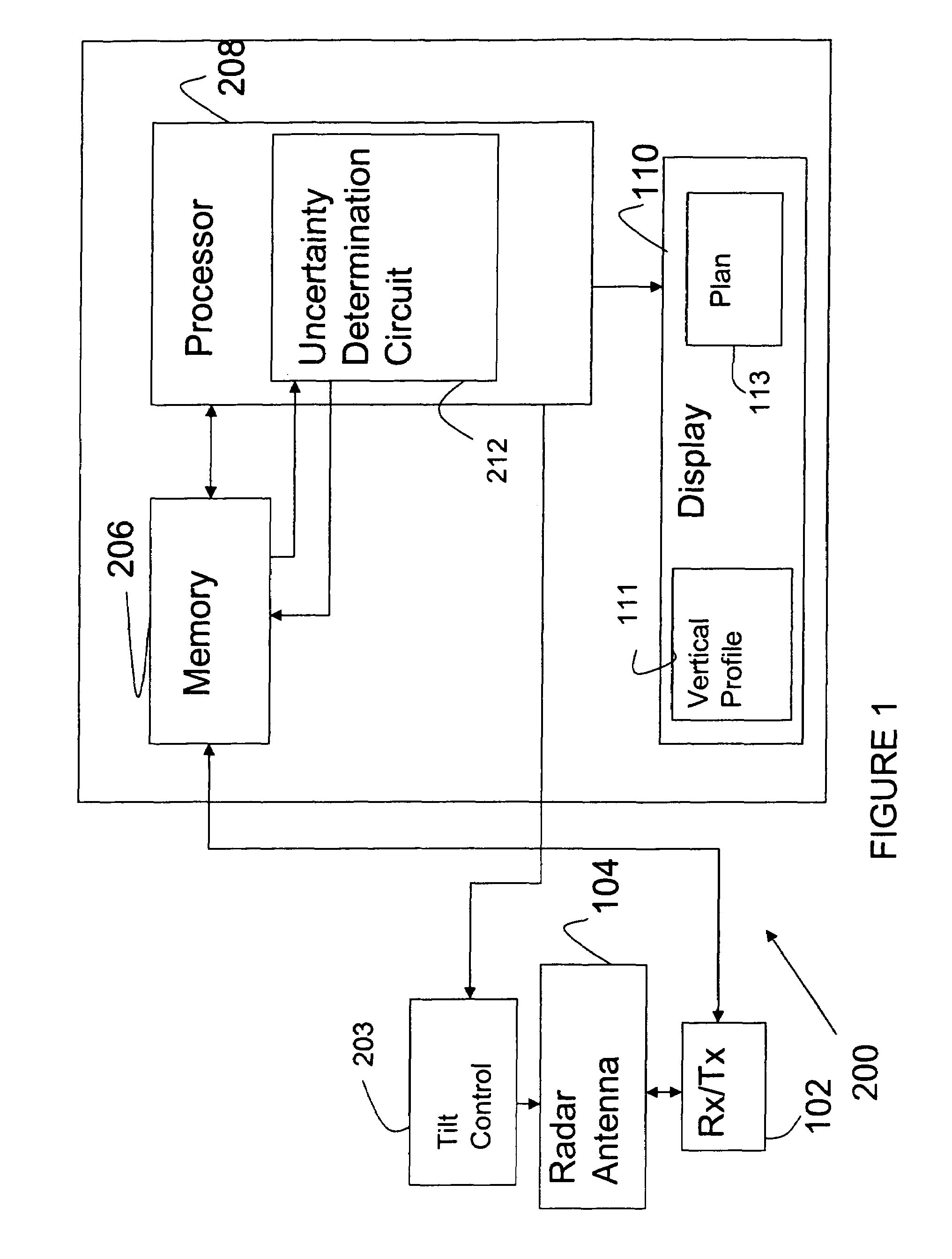
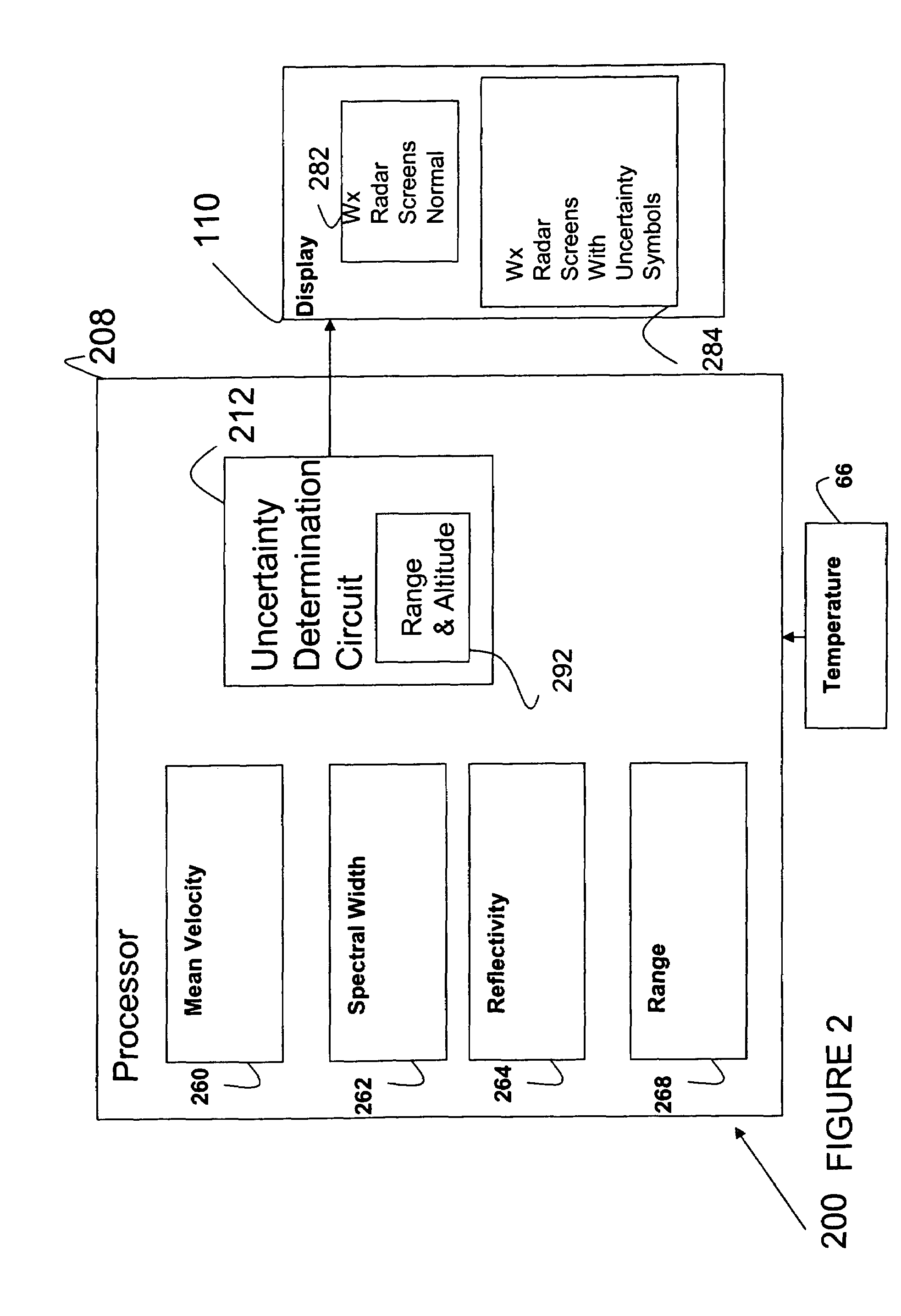
[0022]Before describing in detail the particular improved system and method, it should be observed that the invention includes, but is not limited to a novel structural combination of conventional data / signal processing components and circuits, and not in the particular detailed configurations thereof. Accordingly, the structure, methods, functions, control and arrangement of conventional components and circuits have, for the most part, been illustrated in the drawings by readily understandable block representations and schematic diagrams, in order not to obscure the disclosure with structural details which will be readily apparent to those skilled in the art, having the benefit of the description herein. Further, the invention is not limited to the particular embodiments depicted in the exemplary diagrams, but should be construed in accordance with the language in the claims.

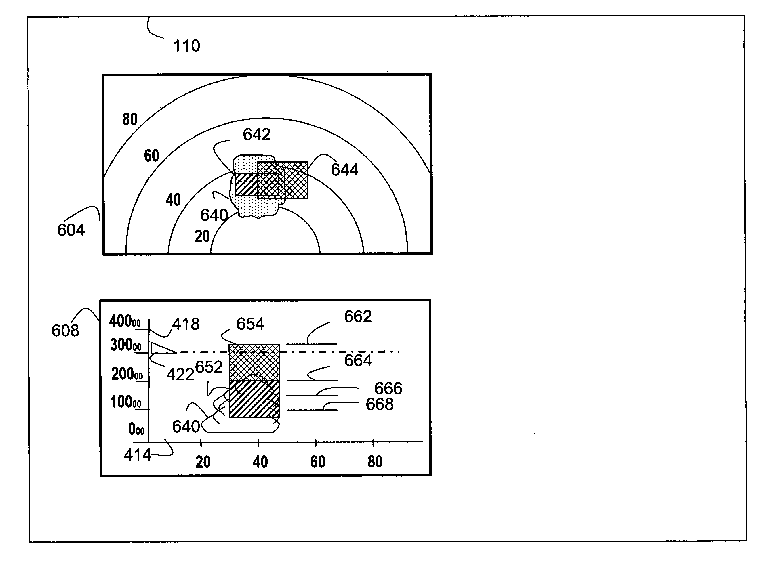
[0023]In conventional aircraft systems, air carriers wish to detect threatening weather which may be a threa...


PUM


Abstract

A weather radar system includes processing electronics. The processing electronics sense weather and determine an uncertainty factor. A display can provide visual indicia of the uncertainty factor for weather in response to the processing electronics. The display can be a vertical profile display. The weather radar system can be an avionic weather radar system.

Description

BACKGROUND[0001]The present application relates to weather radar systems. More particularly, the present application relates to a weather radar system that displays the presence of weather on a screen.[0002]U.S. Pat. No. 6,424,288 invented by Daniel L. Woodell and assigned to the assignee of the present application discloses systems for and methods of displaying radar information using weather radar systems. Weather radar systems generally include an antenna, a receiver / transmitter circuit, a processor, and display. The processor is coupled between the display and the receiver / transmitter circuit. The receiver / transmitter circuit is coupled between the processor and the antenna.[0003]The processor provides transmit signals through the receiver / transmitter circuit to the antenna to transmit radar beams. The processor receives radar return signals derived from radar returns received by the antenna. The radar return signals are provided to the processor via the receiver / transmitter cir...

Claims


Application Information

Patent Timeline
Patent Type & Authority Patents(United States)
IPC IPC(8): G01S13/00
CPCG01S7/064G01S7/18G01S7/22G01S7/24G01S13/953Y02A90/10
Inventor WOODELL, DANIEL L.PARAMORE, STEVEROBERTSON, ROY E.
Owner ROCKWELL COLLINS INC
Why Eureka
Try Eureka