
Slip-over distribution cabinet

a technology of distribution cabinet and slide-over, which is applied in the direction of machine supports, household objects, and switchgear with a removable carriage, etc., can solve the problem that the electrical emission to the outside cannot take place within the prescribed limit valu

Inactive Publication Date: 2009-02-17
ADC GMBH
View PDF33 Cites 33 Cited by
  • Summary
  • Abstract
  • Description
  • Claims
  • Application Information

AI Technical Summary

Benefits of technology

Enables the expansion or replacement of distribution cabinet bodies without the need for new installation approvals, ensuring stability and secure grounding, while maintaining the cabinet's original location and reducing the complexity and time required for the upgrade process.

Problems solved by technology

In addition, modern distribution cabinets are made EMC-proof, with the consequent result that electromagnetic emission to the outside can only take place within the prescribed limit values.
As long as the telecommunication companies were also state-owned, this rarely presented any problems; with increasing privatization, the authorities are refusing installation or demand a fee for installation, quite apart from the fact that an approval procedure has to be undergone and takes considerable time.
This problem arises in the case of all distribution cabinets that are to be newly installed, that is to say in particular in development areas, or if there is no longer any space available for technical components, in particular electrical components, in an existing distribution cabinet and a further distribution cabinet should be additionally set up alongside it.
A further, technical problem exists when an existing distribution cabinet is replaced for technical reasons, that is to say for example if the body of an already existing distribution cabinet has to be exchanged to improve the EMC-proof shielding or the cooling capability.

Method used


Image

  • Slip-over distribution cabinet
  • Slip-over distribution cabinet
  • Slip-over distribution cabinet

Examples


Embodiment Construction

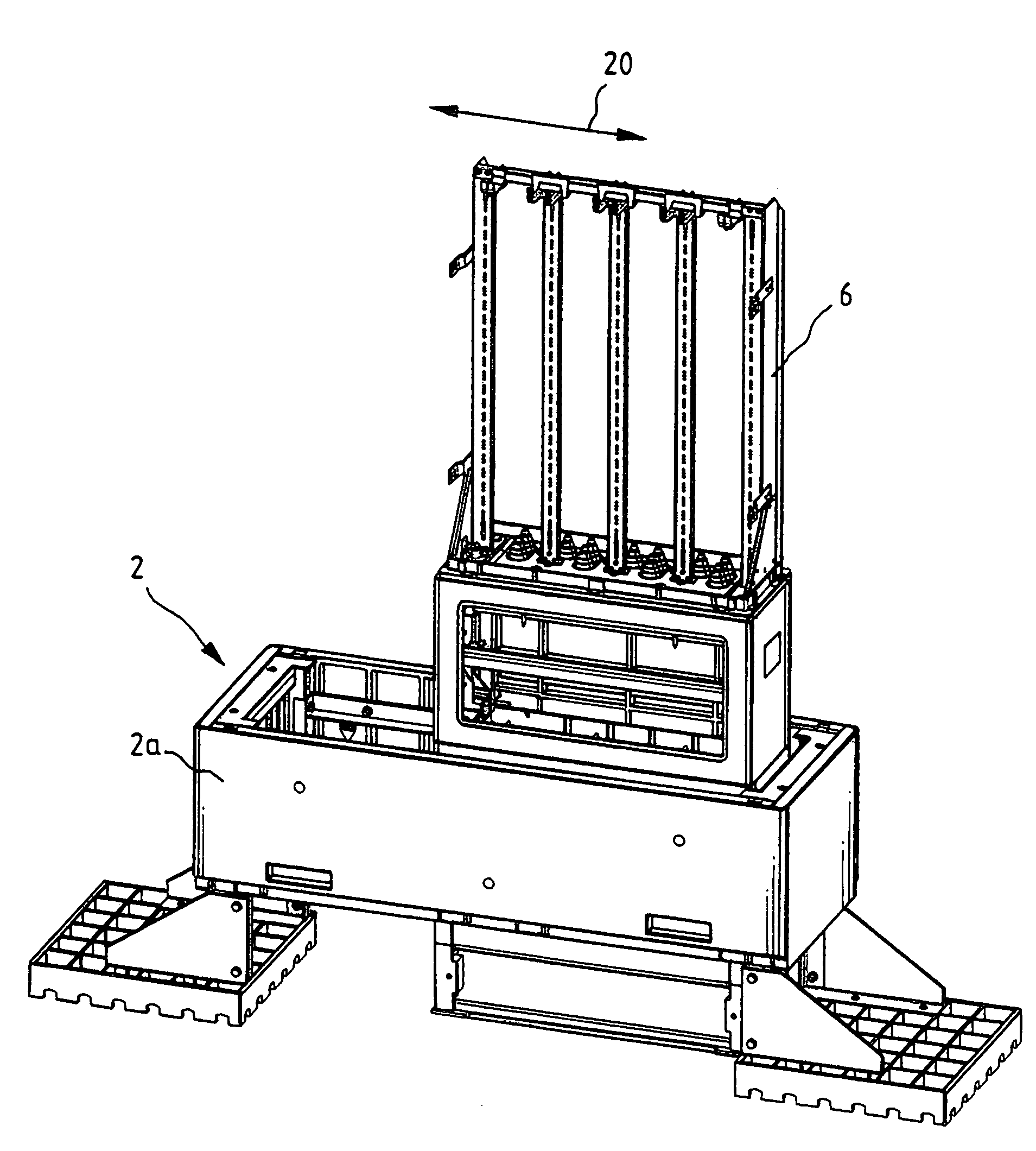
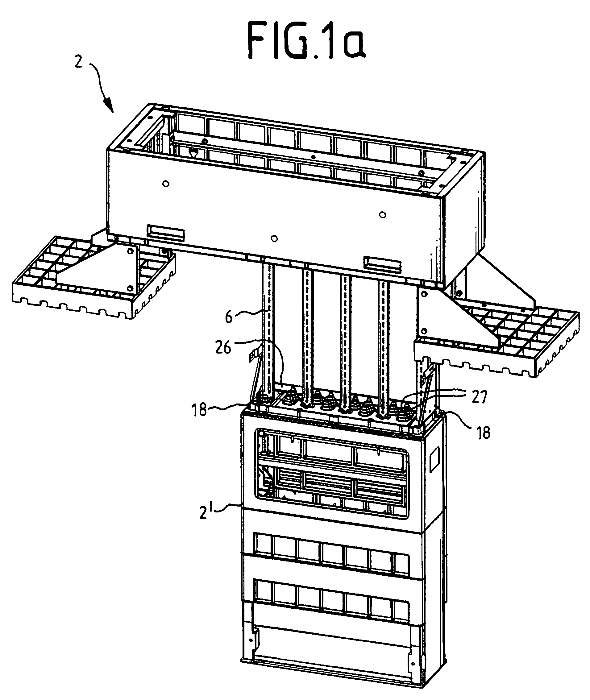
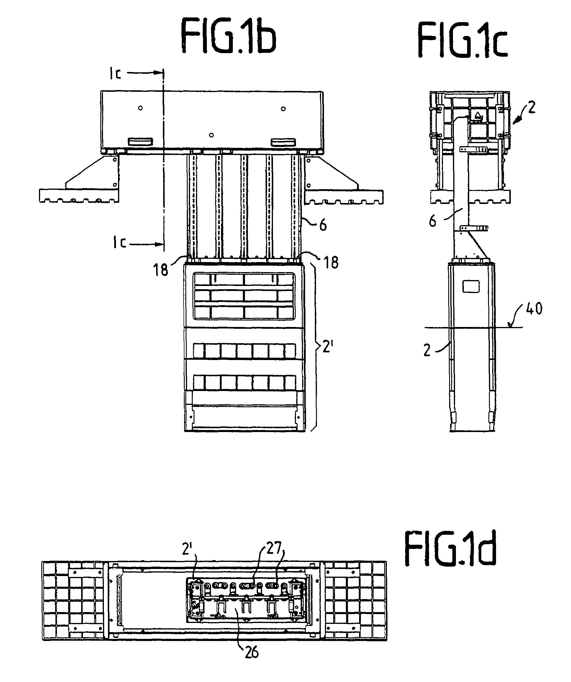
[0049]Before the procedure involved in slipping over the new distribution cabinet is explained on the basis of FIGS. 1 to 6, its individual parts, namely the new base 2 and the new body 3, are described individually on the basis of FIGS. 7 to 13, and the different states of construction of the new body 3 are thereby explained on the basis of FIGS. 7 to 12.

[0050]FIG. 13 shows the new base 2, which is screwed together from a number of individual parts:

[0051]On the one hand, the base box 2a, which is hollow, that is to say open right through when viewed in plan view, and generally consists of plastic, concrete, a mixture of the two or some other non-rusting material. Fastened under its outer side regions in the transverse direction 20, of the greater transverse extent of the base box 2a, are base feet 2b, with which the base box 2a is set down on the underlying ground, which is removed for this purpose down to the desired level.

[0052]The base feet 2b comprise base-foot plates 2d, prefe...


PUM

PropertyMeasurementUnit
sizeaaaaaaaaaa
distanceaaaaaaaaaa
heightaaaaaaaaaa

Abstract

The invention relates to a distribution cabinet which is usually set up outdoors and accommodates the technical, for example electrical or optical, distribution installations for, for example, weak-current systems, for example telephone systems, with associated power-supply devices and cable-terminal / connection devices for a certain area, and also to a method for exchanging, in particular increasing the size of, the body of a distribution cabinet, the exchange of which body is unproblematical and with which method the distribution cabinet remains at the original location and consequently no new installation approval or construction approval is necessary. This takes place by a method for exchanging, in particular increasing the size of, the body of a distribution cabinet set up outdoors in which the body of the old distribution cabinet is removed, a new base, which is hollow when viewed in plan view, is slipped over the old installation frame and the old base and set down on the underlying ground and aligned, and a new body, which has at least as much interior space as the old body, is slipped from above over the old installation frame, aligned and fastened.

Description

APPLICATION AREA[0001]The invention relates to a distribution cabinet which is usually set up outdoors and accommodates the technical, for example electrical or optical, distribution installations for, for example, weak-current systems, for example telephone systems, with associated power-supply devices and cable-terminal / connection devices for a certain area.TECHNICAL BACKGROUND[0002]Nowadays—in addition to having sufficient structural stability and resistance to vandalism, etc.—such distribution cabinets have to satisfy further requirements, for example excessive electromagnetic radiation must not be emitted to the surroundings, and, for use in warmer countries in particular, the temperatures in the interior of the distribution cabinet must not rise to too high a level, despite the heat-emitting electrical subassemblies accommodated there, nor must they drop to too low a level.[0003]Such distribution cabinets are, in principle, produced either from metal or from plastic, plastic c...

Claims


Application Information

Patent Timeline
Patent Type & Authority Patents(United States)
IPC IPC(8): H05K5/04H02B1/50H02B3/00
CPCH02B1/50Y10T29/49826H02B3/00
Inventor IRMER, GUNTERPERSCHON, HELMUT
Owner ADC GMBH
Learn More