
Bidirectional buffered interface for crosspoint switch

a cross-point switch and buffering technology, applied in the field of communication systems and subsystems, can solve problems such as hardware complexity, and achieve the effect of reducing hardware complexity

Inactive Publication Date: 2009-02-17
INTERSIL INC
View PDF1 Cites 0 Cited by
  • Summary
  • Abstract
  • Description
  • Claims
  • Application Information

AI Technical Summary

Benefits of technology

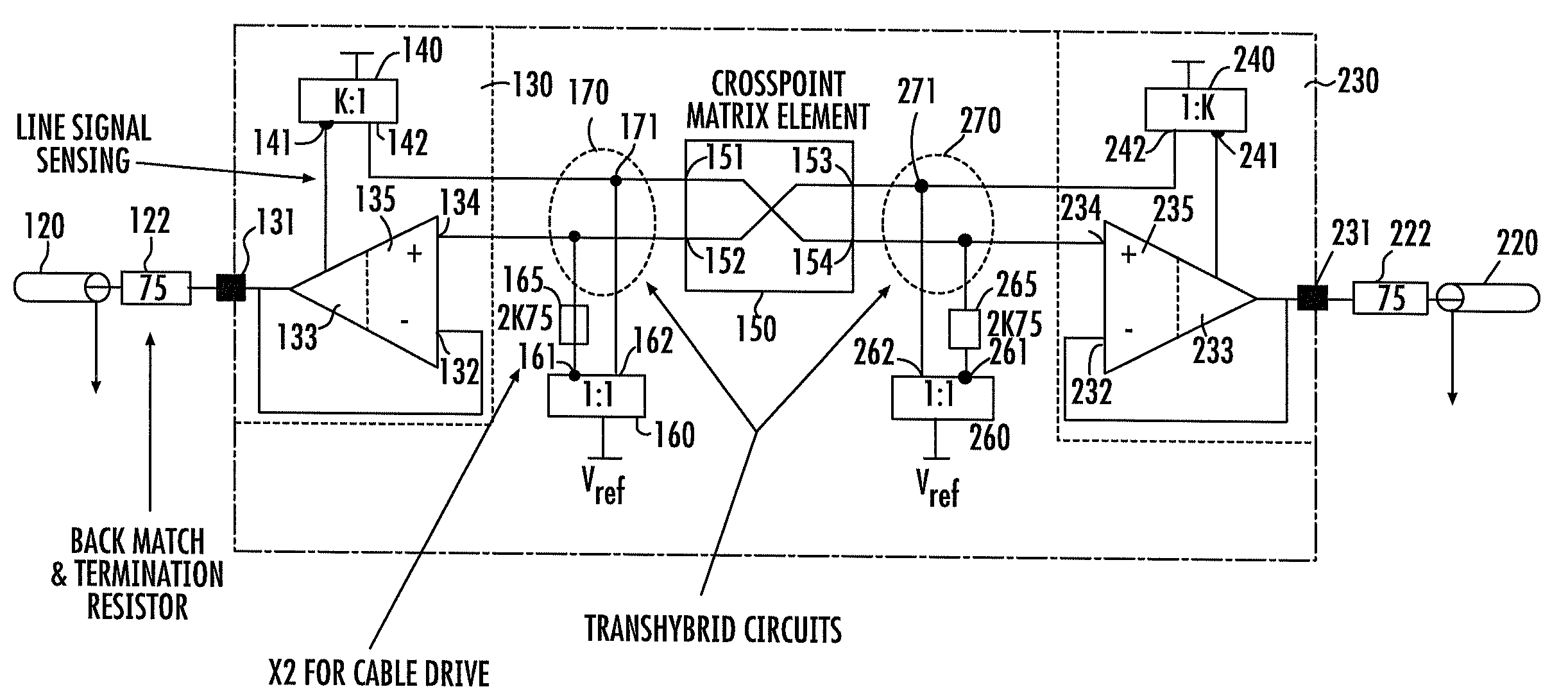
[0010]In accordance with the present invention, advantage is taken of the functionality of a reverse- or backward-connected transimpedance amplifier of the type disclosed in the L. Enriquez U.S. Pat. No. 6,411,163 (hereinafter referred to as the '163 patent and the disclosure of which is incorporated herein), to provide a reduced hardware complexity-based bidirectional crosspoint switch interface, that employs a pair of reverse-configured transimpedance amplifiers of the type disclosed in the '163 patent, and associated current mirrors, interconnected with associated signal cancellation circuits in a manner that affords bidirectional buffering between a crosspoint switch and a pair of bidirectional input / output ports, without signal reflections.
[0011]To this end, a signal transport cable, such as 75 ohm cable, is terminated by way of a (75 ohm) impedance to a relatively ‘west’ end, bidirectional signaling port of an output stage of a first, ‘west’ end transimpedance amplifier, of the type disclosed in the '163 patent, the bidirectional signaling port being coupled to the inverting (−) input terminal of a unity gain stage of the amplifier. The amplifier has its output stage coupled to an input terminal of a ‘west’ end K:1 current mirror, which divides the sensed line current by a factor of K, and reduces the current requirements of the interface.

Problems solved by technology

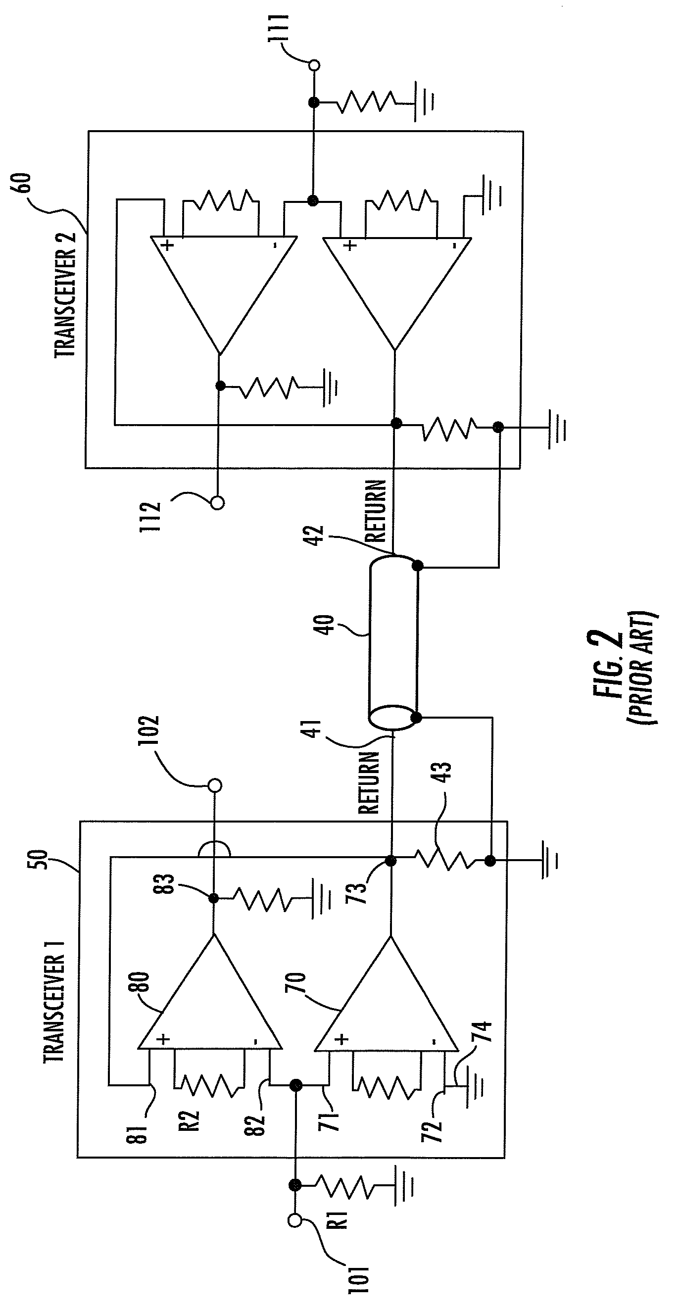
Now although the transceiver architecture of FIG. 2 provides an interface for bidirectional signaling, it is hardware intensive—requiring two transconductance amplifiers per transceiver—and requires a substantial signal drive, since driving the signal line also entails driving a termination impedance (e.g., 50 ohm resistor) to ground.

Method used


Image

  • Bidirectional buffered interface for crosspoint switch
  • Bidirectional buffered interface for crosspoint switch
  • Bidirectional buffered interface for crosspoint switch

Examples


Embodiment Construction

Architecture

[0023]As pointed out briefly above, pursuant to the present invention, advantage is taken of the functionality of a reverse- or backward-connected transimpedance amplifier of the type disclosed in the '163 patent, to provide a reduced hardware complexity architecture for realizing full bidirectional signaling capability through a crosspoint switch. This new and improved bidirectional buffered interface architecture according to a preferred, but non-limiting, embodiment of the present invention is diagrammatically illustrated in FIG. 3, which shows a (75 ohm) cable 120 terminated by way of a (75 ohm) impedance 122 to a relatively ‘west’ end input / output (bidirectional signaling) port 131 of an output stage 133 of a first, ‘west’ end transimpedance amplifier 130, of the type disclosed in the '163 patent.

[0024]The input / output port 131 of ‘west’ end transimpedance amplifier 130 is coupled to the inverting (−) input terminal 132 of a unity gain stage 135 of the amplifier. Th...


PUM


Abstract

A bidirectional crosspoint switch interface employs a pair of backward-connected transimpedance amplifiers of the type disclosed in the L. Enriquez U.S. Pat. No. 6,411,163, and associated scaling current mirrors that drive nodes of associated reverse signal cancellation circuits. The reverse signal cancellation circuits are coupled to respective pairs of ports of the crosspoint switch and input and output ports of 1:1 current mirrors, in a manner that affords bidirectional buffering between the crosspoint switch and a pair of bidirectional signaling ports that terminate respective signaling links, without signal reflections.

Description

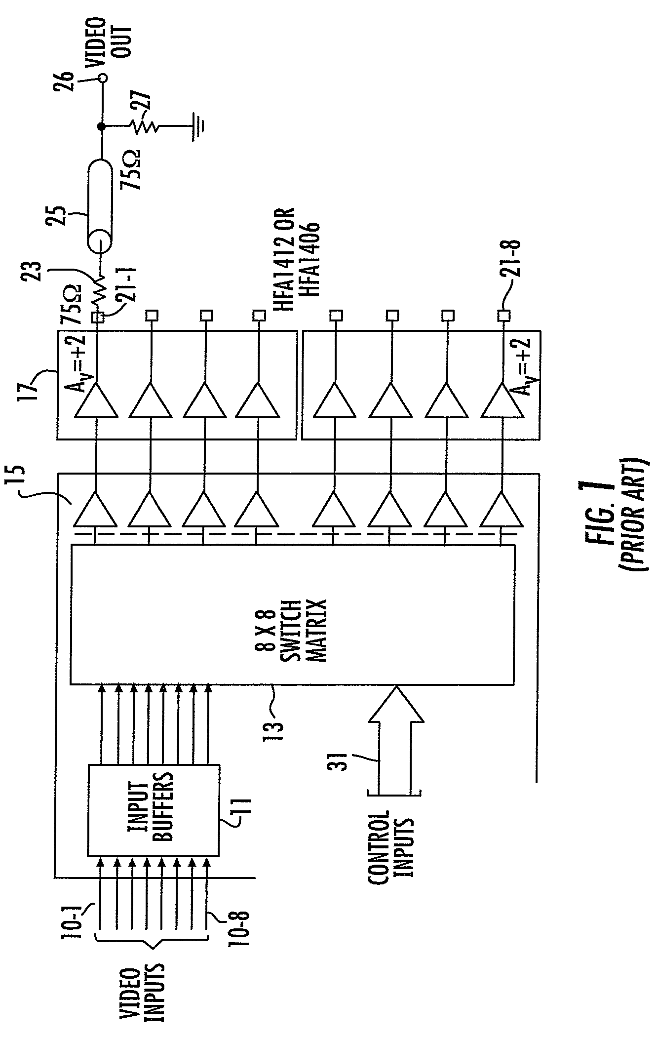
CROSS-REFERENCE TO RELATED APPLICATION[0001]The present application claims the benefit of U.S. Application, Ser. No. 60 / 671,719, filed Apr. 15, 2005, by Christopher Ludeman, entitled: “Bidirectional Buffered Interface for Crosspoint Switch,” assigned to the assignee of the present application and the disclosure of which is incorporated herein.FIELD OF THE INVENTION[0002]The present invention relates in general to communication systems and subsystems and circuits thereof, and is particularly directed to a reduced hardware complexity-based bidirectional crosspoint switch interface, that employs a pair of reverse-configured transimpedance amplifiers and associated current mirrors, that provide bidirectional buffering between a crosspoint switch device and a pair of bidirectional input / output ports.BACKGROUND OF THE INVENTION[0003]FIG. 1 diagrammatically illustrates the overall system configuration of a conventional multiport crosspoint switch architecture of the type that may be used f...

Claims


Application Information

Patent Timeline
Patent Type & Authority Patents(United States)
IPC IPC(8): H04B3/00H04L25/00
CPCH04B3/03H04Q2213/1302H04Q2213/1304H04Q2213/1319H04Q2213/13306H04Q2213/1332
Inventor LUDEMAN, CHRISTOPHER
Owner INTERSIL INC
Learn More