Undercut screw and matching bit

a screw and screw technology, applied in the direction of screwdrivers, wrenches, fastening means, etc., can solve the problems of difficult to stop the driver, difficult to remove the screw, and destroying the bit, and achieve the effect of convenient operation

Inactive Publication Date: 2009-02-24
FUERLE RICHARD D
View PDF17 Cites 10 Cited by
  • Summary
  • Abstract
  • Description
  • Claims
  • Application Information

AI Technical Summary

Benefits of technology

[0006]Like the screw and bit disclosed in the parents of this application, the bit of this invention is easily inserted directly into the undercut slot in the head of the screw, the bit applies torque to the periphery of the head of the screw, not near the center, and the bit cannot be easily removed from the slot in a vertical (z-axis) or horizontal (x or y-axis) direction once the bit has been turned. But unlike the screw in those inventions, the screw of this invention can be easily made by cold heading.

Problems solved by technology

Power screwdrivers can produce greater torque than can a human, but if the rotation of the driver is not stopped immediately when the bottom of the head of the screw hits the surface into which the screw is being driven, both the slot in the screw and the bit can be stripped, destroying the bit and making it difficult to remove the screw.
It is not easy to stop the driver just when the head of the screw contacts the surface, so stripped screws and ruined bits are common.
This is especially true of Phillips screwdrivers (X-shaped slots) and square drives (where the slot is a square well) because the bit engages the slot so close to the center of the head of the screw that there is very little mechanical advantage.
In addition, the torque of the driver tends to force the bit out of the slot, so that the operator must apply considerable pressure to keep the bit in the slot.
While the use of the protuberance and well is an improvement over the screw and bit of U.S. Pat. No. 6,526,851, the screws of both U.S. patent application Ser. No. 10 / 248,790 and U.S. Pat. No. 6,526,851 are difficult to manufacture using cold heading, the most common technology for making inexpensive screws.

Method used


Image

  • Undercut screw and matching bit
  • Undercut screw and matching bit
  • Undercut screw and matching bit

Examples


Embodiment Construction

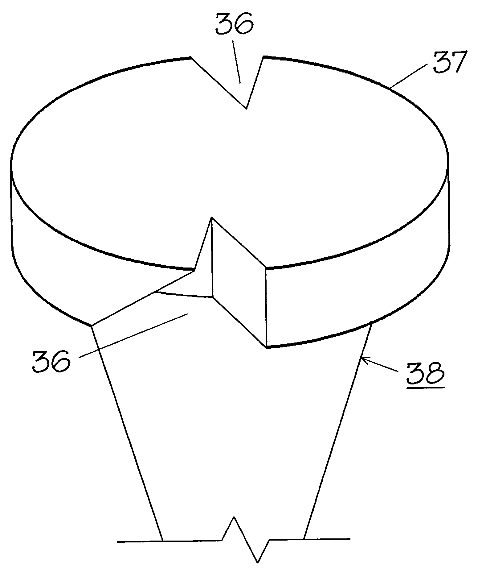
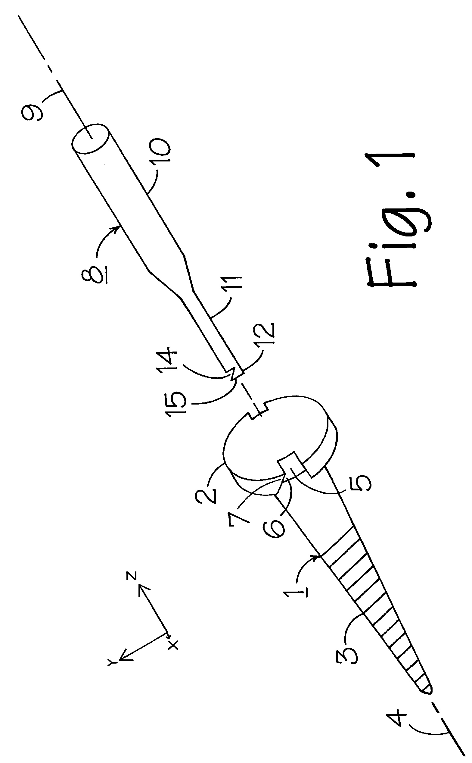
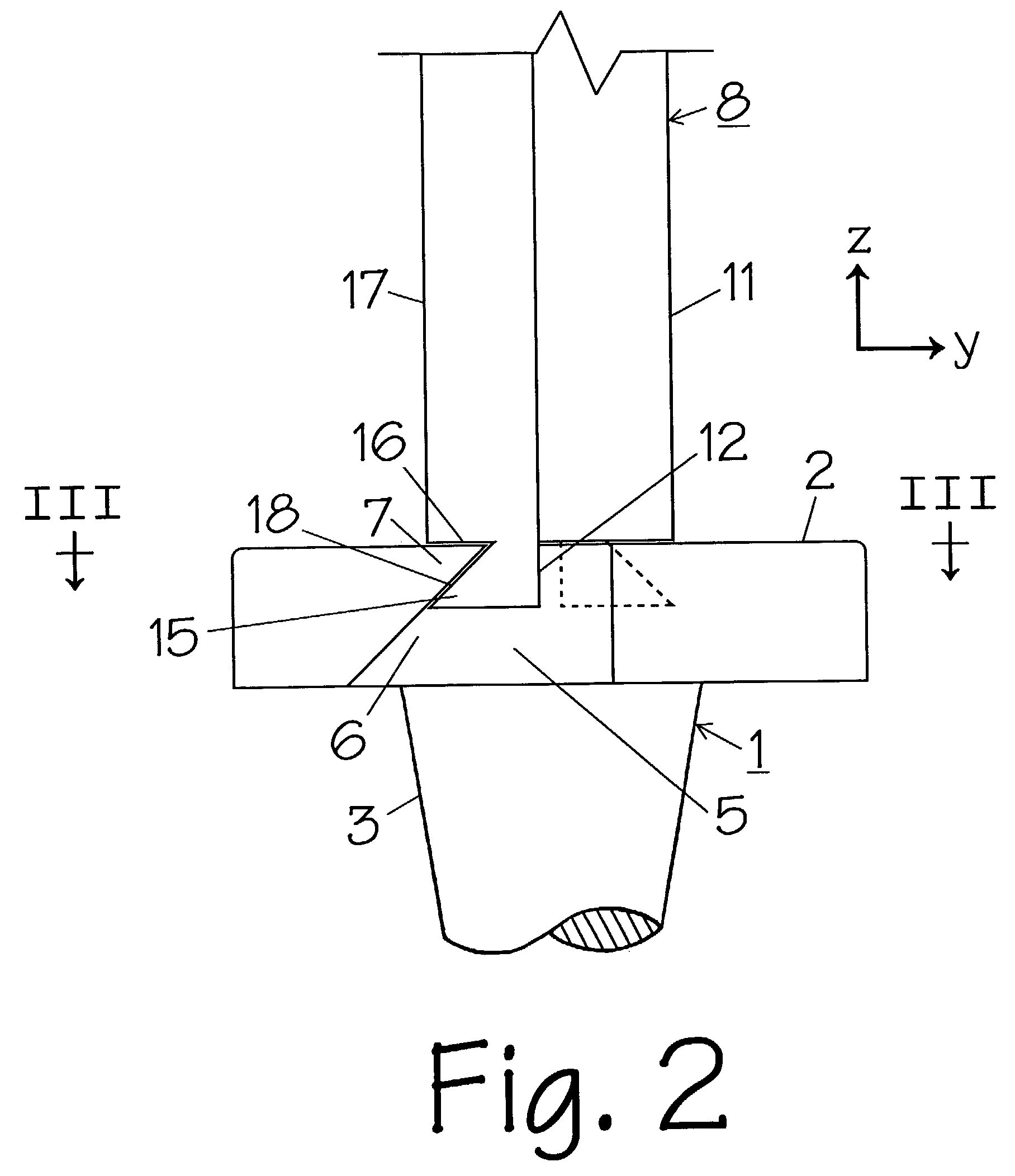
[0020]In FIGS. 1, 2, 3, and 4, pan head screw 1 has a head 2 and threaded shaft 3 and is centered on longitudinal axis 4. At the periphery of a diameter of head 2 are two slots 5, which extend completely through head 2 of screw 1. By positioning dies in the shape of slots 5 around a wire blank, screw 1 can be made by cold heading. Slots 5 may have a variety of shapes and dimensions appropriate for the type of screw to be used. A slot bound on three sides by the head of the screw (as in FIG. 1) may have a width (tangential direction) of about 1 / 32 to about ¼ inches. (A “tangential” direction is a direction approximately tangent to the periphery of the head of the screw, i.e., a direction that will turn the screw clockwise or counterclockwise.) Each slot 5 has an undercut portion 6 on one side, the side to which clockwise torque is applied to head 1. The undercut portions 6 form wedges 7; the peak of each wedge points in a counterclockwise direction. (If a counterclockwise torque is t...


PUM


Abstract

A threaded fastener, such as a screw or a bolt, has a central longitudinal axis in a z-axis direction. The fastener has a head and a threaded shaft. The head has an overhanging periphery in an x-y plane and at least two slots, evenly-spaced apart, that extend completely through the overhanging periphery. Each slot has a sloped surface that undercuts the overhanging periphery in the same tangential direction. The screw is turned by using a bit that has a central longitudinal axis in a z-axis direction. The bit has a shank fixed to an end portion and at least two legs, evenly-spaced apart, extend from the end portion in a z-axis direction. Each leg has a sloped surface that extends in the same tangential direction.

Description

CROSS REFERENCE TO RELATED APPLICATIONS[0001]This application is a continuation-in-part of application Ser. No. 10 / 248,790, filed Feb. 19, 2003, which is a continuation-in-part of application Ser. No. 10 / 064,150, filed Jun. 14, 2002, issued Mar. 4, 2003 as U.S. Pat. No. 6,526,851.BACKGROUND OF INVENTION[0002]This invention relates to a novel screw and matching novel bit. In particular, it relates to a screw having at least two undercut slots at the periphery of its head, and to a bit that engages those slots.[0003]Power screwdrivers are now used more and more, especially when a large number of screws must be fastened. Power screwdrivers can produce greater torque than can a human, but if the rotation of the driver is not stopped immediately when the bottom of the head of the screw hits the surface into which the screw is being driven, both the slot in the screw and the bit can be stripped, destroying the bit and making it difficult to remove the screw. It is not easy to stop the dri...

Claims


Application Information

Patent Timeline
Patent Type & Authority Patents(United States)
IPC IPC(8): F16B23/00B25B23/08B25B15/00
CPCB25B15/007F16B23/0015Y10S411/919
Inventor FUERLE, RICHARD D.
Owner FUERLE RICHARD D
Why Eureka
Try Eureka