Method and apparatus for providing a short-stemmed hip prosthesis

Inactive Publication Date: 2009-02-24
BIOMET MFG CORP
View PDF51 Cites 43 Cited by
  • Summary
  • Abstract
  • Description
  • Claims
  • Application Information

AI Technical Summary

Problems solved by technology

Because conventional hip replacement procedures typically removes a relatively significant amount of bone tissue from the area surrounding the proximal intramedullary canal, there is less bone and are significant problems associated with securing the revision prosthesis to the remaining femoral structure.

Method used


Image

  • Method and apparatus for providing a short-stemmed hip prosthesis
  • Method and apparatus for providing a short-stemmed hip prosthesis
  • Method and apparatus for providing a short-stemmed hip prosthesis

Examples


Embodiment Construction

[0049]The following description of the preferred embodiments concerning a method and apparatus for providing a short-stemmed femoral insert for use in orthopedic surgical procedures are merely exemplary in nature and are not intended to limit the invention or its application or uses. Moreover, while the present invention is described in detail below with reference to performing a primary type implantation procedure, it will be appreciated by those skilled in the art that the present invention is clearly not limited to only primary type orthopedic surgical procedures and may be used with various other orthopedic surgical procedures as well, including revision type orthopedic surgical procedures.

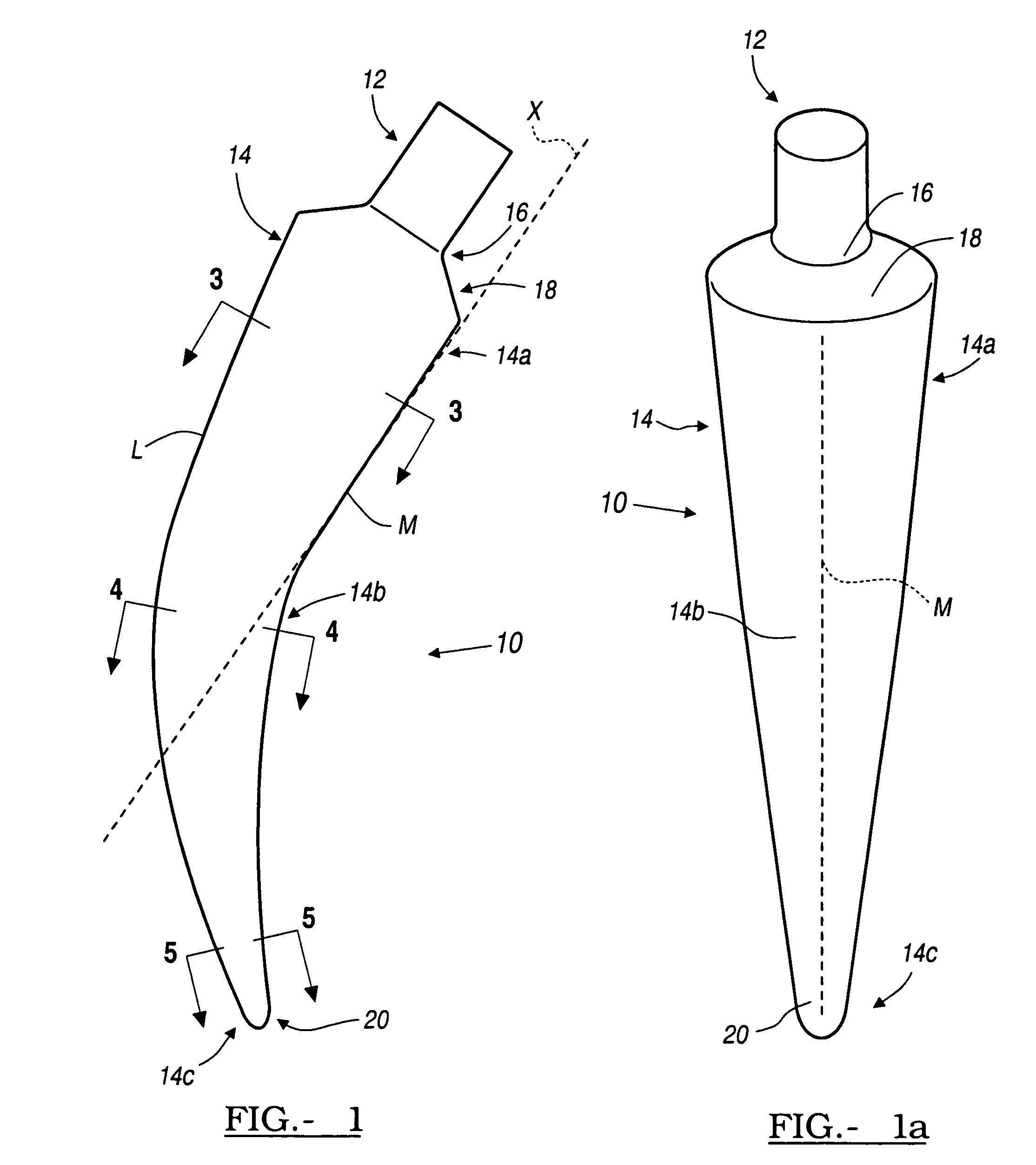
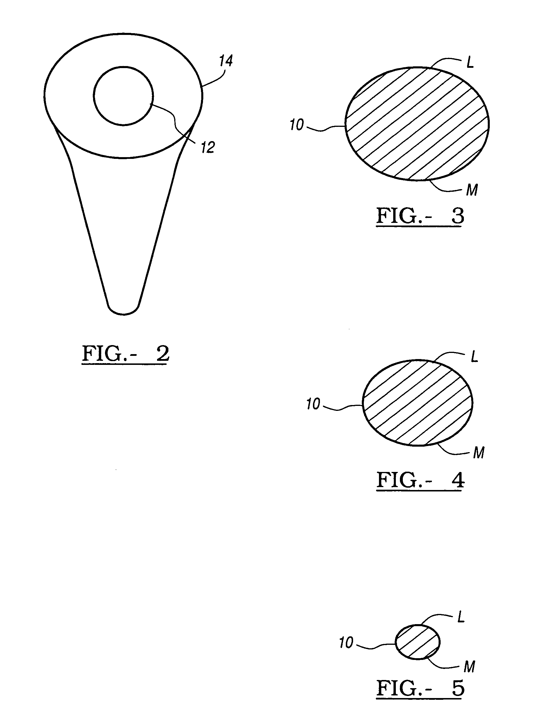
[0050]Referring to FIGS. 1-5, there is generally shown a femoral insert 10, in accordance with one embodiment of the present invention. The femoral insert 10 is preferably comprised of a biocompatible material, such as titanium alloys, stainless steel, chrome-cobalt alloys, and the like. The f...


PUM

PropertyMeasurementUnit
Angleaaaaaaaaaa
Shapeaaaaaaaaaa
Radiusaaaaaaaaaa

Abstract

A method of implanting at least a stem member of a femoral insert into an intramedullary canal of a femur. The method includes making an anterior incision for accessing the intramedullary canal, and inserting a stem member of the femoral insert into the intramedullary canal through the incision along an arcuate path defined by an arcuate profile of the stem member.

Description

CROSS-REFERENCE TO RELATED APPLICATIONS[0001]This application is a continuation-in-part of U.S. patent application Ser. No. 10 / 066,996 filed on Feb. 4, 2002. The disclosure of the above application is incorporated herein by reference.FIELD OF THE INVENTION[0002]This invention relates generally to a method and apparatus for use in orthopedic surgery and, more particularly, to a method and apparatus for providing a short-stemmed hip prosthesis having a substantially constant radius over at least a portion thereof to ease insertion into bone, a raised lateral lip to resist rotation, and a biplanar taper to conserve bone tissue and promote gradual stress transfer.BACKGROUND OF THE INVENTION[0003]A natural hip joint may undergo degenerative changes due to a variety of etiologies. When these degenerative changes become so far advanced and irreversible, it may ultimately become necessary to replace a natural hip joint with a prosthetic hip. When implantation of such a hip joint prosthesis ...

Claims


Application Information

Patent Timeline
IPC IPC(8): A61F2/36A61F2/32
CPCA61F2/3662A61F2/3601A61F2002/30172A61F2002/3069A61F2002/30769A61F2002/365A61F2002/3668A61F2230/0052A61F2310/00017A61F2310/00023A61F2310/00029A61F2310/00407A61F2002/30884
Inventor HERSHBERGER, TROY WLAKIN, RYAN C
Owner BIOMET MFG CORP
Why Eureka
Try Eureka