Program and erase methods and structures for byte-alterable flash memory

a technology of byte-alterable flash memory and program and erase methods, which is applied in the field of integrated circuits, can solve the problems of reducing increasing the overall time for erase operations, so as to reduce undesirable erase and program operations, reduce operation time, and increase the lifetime of flash memory cells

Active Publication Date: 2009-02-24
TAIWAN SEMICON MFG CO LTD
View PDF3 Cites 13 Cited by
  • Summary
  • Abstract
  • Description
  • Claims
  • Application Information

AI Technical Summary

Benefits of technology

[0011]The advantageous features of the present invention include reducing undesirable erase and program operations so that not only is the operation time reduced, but the lifetime of the flash memory cells is increased.

Problems solved by technology

This not only causes an increase in the overall time for erase operations, but also in a reduction in the lifetime of the flash memory cells due to multiple undesirable program and erase operations.

Method used


Image

  • Program and erase methods and structures for byte-alterable flash memory
  • Program and erase methods and structures for byte-alterable flash memory
  • Program and erase methods and structures for byte-alterable flash memory

Examples


Embodiment Construction

[0017]The making and using of the presently preferred embodiments are discussed in detail below. It should be appreciated, however, that the present invention provides many applicable inventive concepts that can be embodied in a wide variety of specific contexts. The specific embodiments discussed are merely illustrative of specific ways to make and use the invention, and do not limit the scope of the invention.

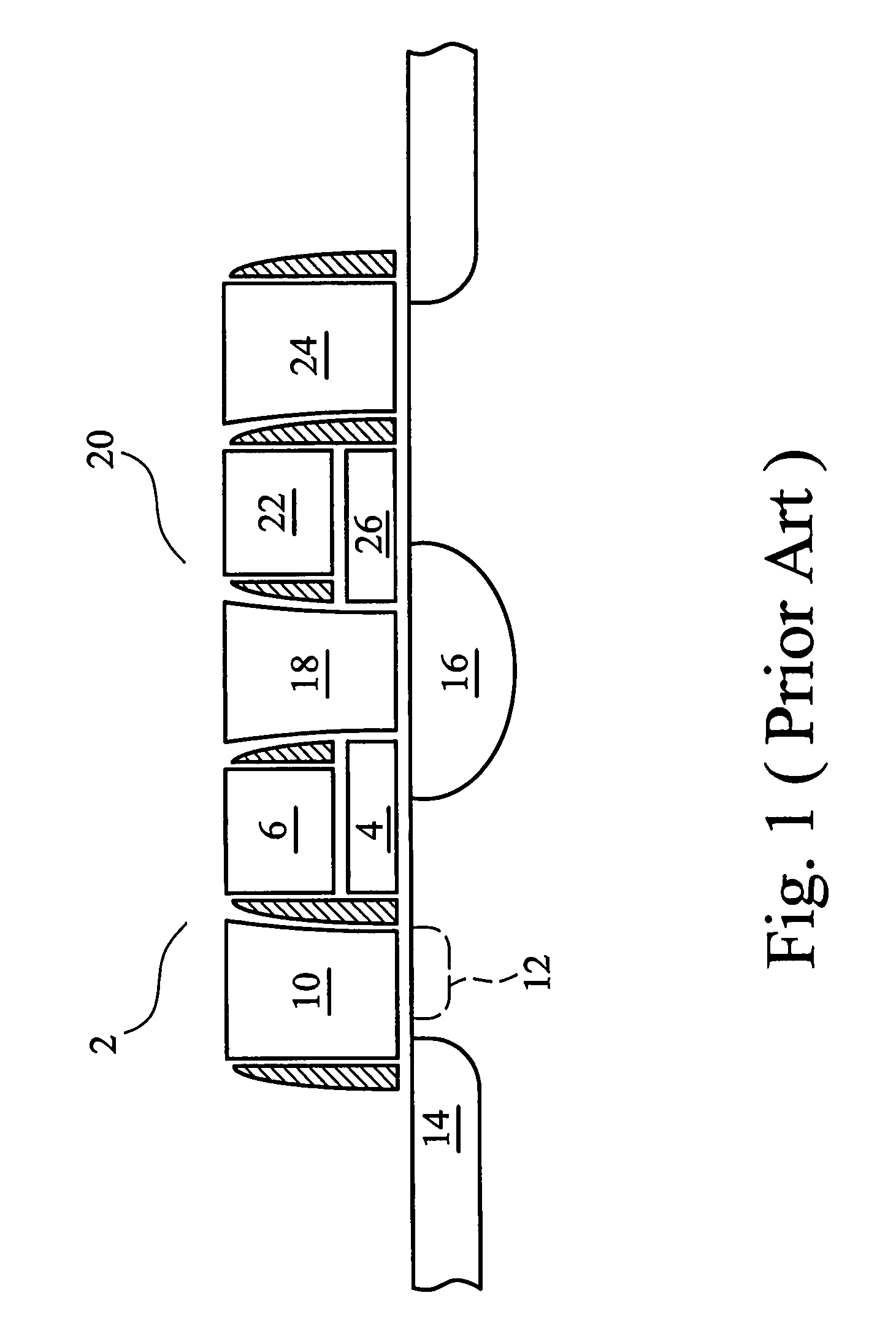
[0018]FIG. 3 illustrates a cross-sectional view of an exemplary flash memory cell pair, which is used for the discussion of the embodiments of the present invention. A first flash memory cell 40 includes floating gate 42, control-gate 44 (sometimes referred to as a coupling-gate 44) over floating gate 42, word-line node 46 adjacent sidewalls of floating gate 42 and control-gate 44, and bit-line node 48 and common source node 50 in a substrate 54. A second flash memory cell 60 includes floating gate 62, control-gate 64 over floating gate 62, word-line node 66 adjacent sidewall...


PUM

PropertyMeasurementUnit
voltageaaaaaaaaaa
voltageaaaaaaaaaa
voltageaaaaaaaaaa

Abstract

An array of flash memory cells arranged in a plurality of rows and a plurality of columns includes a first row comprising a plurality of units. Each unit includes a plurality of flash memory cells, an erase-gate line connecting erase-gates of all flash memory cells in the first row, a source line connecting source nodes of all flash memory cells in the first row, a word line connecting word-line nodes of all flash memory cells in the first row, and a local control-gate (CG) line connecting control-gates of flash memory cells only in the unit, wherein each local CG line is disconnected from remaining local CG lines in the first row. The array further includes bit-lines each connecting bit-line nodes of flash memory cells in a same column.

Description

TECHNICAL FIELD[0001]This invention relates generally to integrated circuits, and more particularly to structures and operating methods of flash memory arrays.BACKGROUND[0002]Flash memory has become increasingly popular in recent years. A typical flash memory comprises a memory array having a large number of memory cells arranged in blocks. Each of the memory cells is fabricated as a field-effect transistor having a control-gate and a floating gate. The floating gate is capable of holding charges and is separated from source and drain regions contained in a substrate by a layer of thin oxide. Each of the memory cells can be electrically charged by injecting electrons from the drain region through the oxide layer onto the floating gate. The charges can be removed from the floating gate by tunneling the electrons to the source through the oxide layer during an erase operation. The data in a memory cell is thus determined by the presence or absence of a charge on the floating gate.[000...

Claims


Application Information

Patent Timeline
Patent Type & Authority Patents(United States)
IPC IPC(8): G11C16/04
CPCG11C16/0433Y10T29/49002
Inventor CHIH, YUE-DER
Owner TAIWAN SEMICON MFG CO LTD
Why Eureka
Try Eureka