Phase locked loop and method for evaluating a jitter of a phase locked loop

a phase locked loop and phase noise technology, applied in the field can solve the problems of widening the spectrum of oscillator signals, phase noise measurement of phase locked loops is only possible with great complexity

Inactive Publication Date: 2009-02-24
INTEL CORP
View PDF16 Cites 6 Cited by
  • Summary
  • Abstract
  • Description
  • Claims
  • Application Information

AI Technical Summary

Benefits of technology

[0015]In another example, the output of the phase detector is coupled to the control input of the oscillator via a first charge pump and a second charge pump connected in parallel with the first charge pump. In this case, the second charge pump is designed for outputting a signal that is proportional to the control signal output by the phase detector. This significantly increases the stability of the regulation on account of the two charge pumps. It is advantageous, moreover, for the two charge pumps, which may also be constructed identically, to be connected to the phase detector with respectively interchanged inputs and outputs. Thus, a first input of a first charge pump is connected to a first output terminal of the phase detector and a second input of the first charge pump is connected to a second output terminal of the phase detector. A first and a second input of the second charge pump are respectively connected to the second and first output terminal of the phase detector.
[0018]It is furthermore expedient to feed the phase detector and also the pulse width generator with a reference signal. In this case, the phase detector compares the phase of the reference signal with the fed-back oscillator signal, and the pulse width generator uses the reference signal for generating a reference pulse. In a suitable embodiment, this enables a fixed phase relationship between the reference pulse and the actuating signal output by the phase detector.
[0020]This allows an assessment of a temporal profile of the evaluation signal for an evaluation of a jitter of the phase locked loop. Such an assessment permits a precise evaluation of the phase noise and of the jitter performance of the phase locked loop in a manner dependent on the pulse width of the reference pulse and also the observation time duration.

Problems solved by technology

However, small current and voltage fluctuations in the oscillator generate a phase noise in the output signal, thereby widening the spectrum of the oscillator signal.
However, a phase noise measurement of a phase locked loop is possible only with great complexity.

Method used


Image

  • Phase locked loop and method for evaluating a jitter of a phase locked loop
  • Phase locked loop and method for evaluating a jitter of a phase locked loop
  • Phase locked loop and method for evaluating a jitter of a phase locked loop

Examples


Embodiment Construction

[0025]One or more aspects of the present invention will now be described with reference to the drawing figures, wherein like reference numerals are used to refer to like elements throughout. It should be understood that the drawing figures and following descriptions are merely illustrative and that they should not be taken in a limiting sense. In the following description, for purposes of explanation, numerous specific details are set forth in order to provide a thorough understanding of the present invention. It will be evident to one skilled in the art, however, that the present invention may be practiced without these specific details. Thus, it will be appreciated that variations of the illustrated systems and methods apart from those illustrated and described herein may exist and that such variations are deemed as falling within the scope of the present invention and the appended claims.

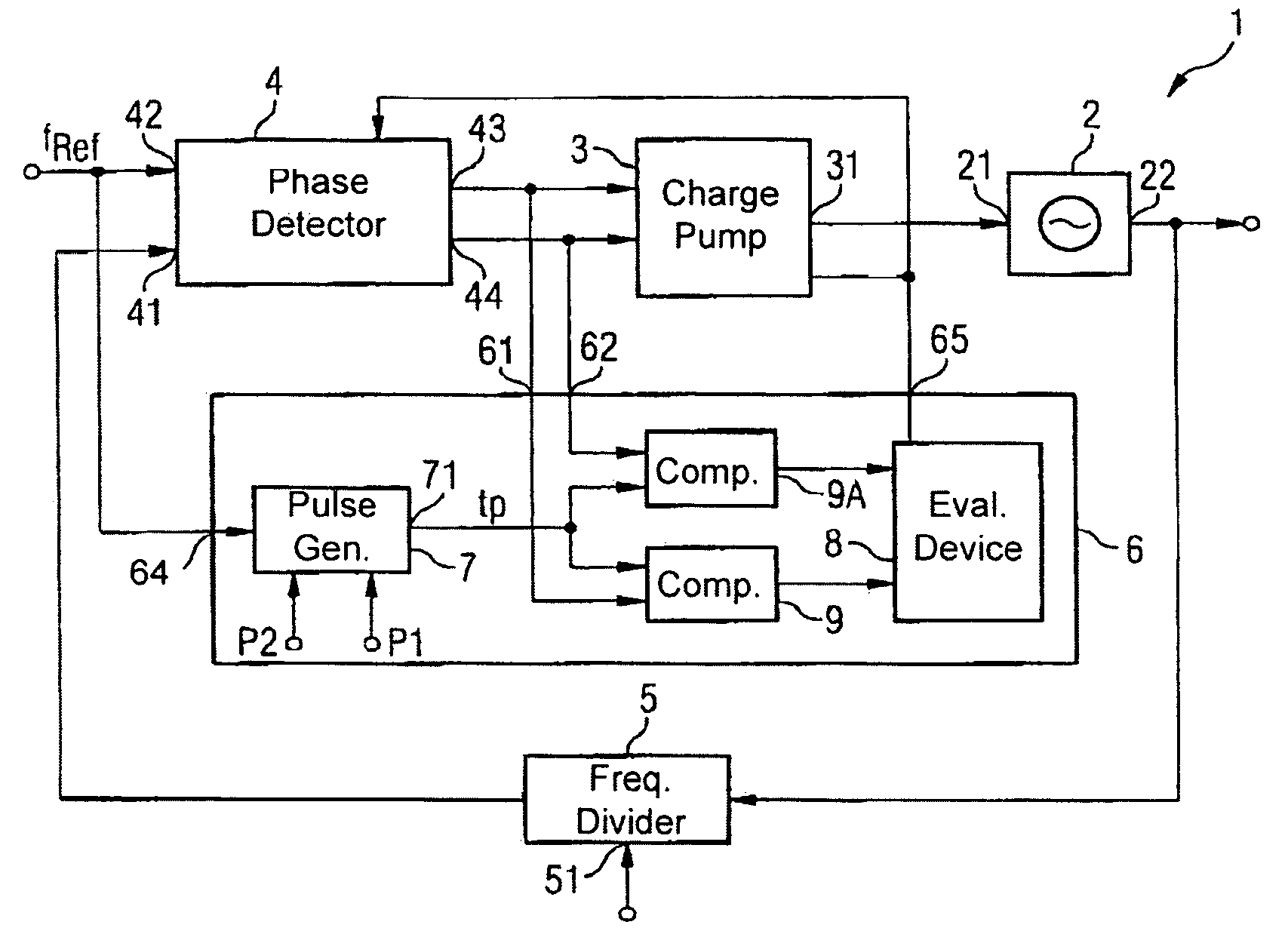
[0026]FIG. 1 illustrates a phase locked loop 1 according to one or more aspects of the presen...


PUM


Abstract

A phase locked loop is disclosed having a phase detector and a controllable oscillator coupled to the detector. A frequency divider is also included in a feedback path of the phase locked loop. The phase locked loop further comprises an evaluation means that facilitates an evaluation of a jitter of the phase locked loop. This allows an on-chip evaluation of the jitter of a phase locked loop to be performed.

Description

REFERENCE TO RELATED APPLICATIONS[0001]This application claims the benefit of the priority date of German application DE 10 2004 007 648.0, filed on Feb. 17, 2004, the contents of which are herein incorporated by reference in their entirety.FIELD OF THE INVENTION[0002]The invention relates generally to a phase locked loop, and more particularly to evaluating a jitter of a phase locked loop.BACKGROUND OF THE INVENTION[0003]Phase locked loops are used primarily for locking on and holding a frequency of an oscillator with respect to a fixedly determined reference frequency. A high frequency stability and phase stability of the oscillator are achieved thereby. One example of a phase locked loop is included in: Gehrung, Bressler, Gutekunst, “Elektronik für Ingenieure” [Electronics for Engineers], 3rd edition, Springer, 1998, on pages 509-519, which schematically shows a basic circuit of a phase locked loop, called PLL for short.[0004]The PLL shown therein comprises a forward path having ...

Claims


Application Information

Patent Timeline
Patent Type & Authority Patents(United States)
IPC IPC(8): H04B3/46H03D3/24G01R29/02H03L7/08H03L7/089
CPCH03L7/0891H03L7/0893
Inventor LINDNER, MANFREDSCHWENK, ROLAND
Owner INTEL CORP
Why Eureka
Try Eureka