Tubular heater with insulating material in the connection end region

a tubular heater and connection end technology, applied in the field of heating equipment, can solve the problems of large addition of tolerances, large cost increase of previously known heating equipment, and known heating equipment, and achieve the effect of reducing costs

a tubular heater and connection end technology, applied in the field of heating equipment, can solve the problems of large addition of tolerances, large cost increase of previously known heating equipment, and known heating equipment, and achieve the effect of reducing costs

US7496284B2Inactive Publication Date: 2009-02-24BLECKMANN

Image

  • Tubular heater with insulating material in the connection end region
  • Tubular heater with insulating material in the connection end region
  • Tubular heater with insulating material in the connection end region

Examples


Embodiment Construction

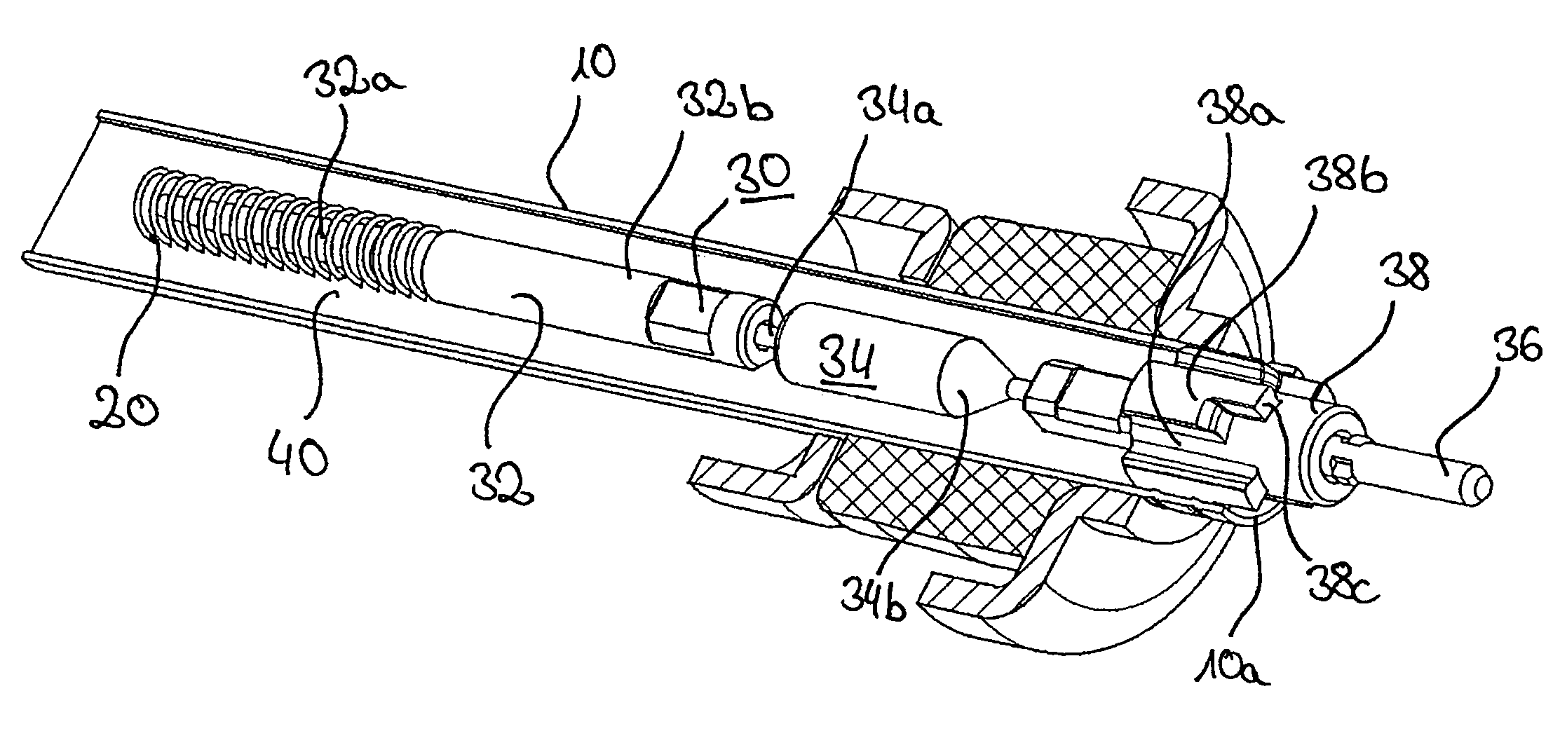
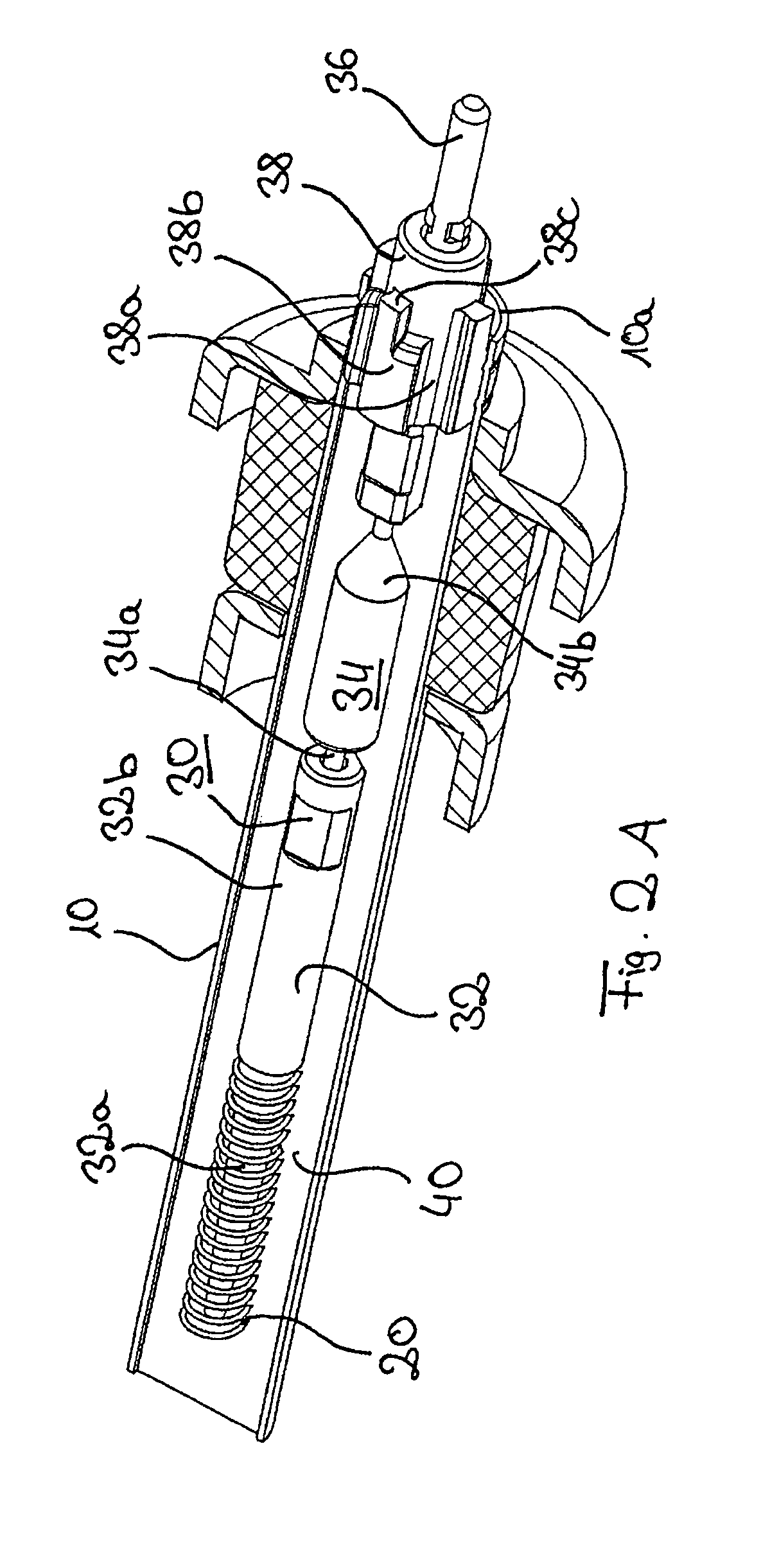
[0022]One embodiment of the heating apparatus which is shown in partial longitudinal section in FIGS. 2A and 2B has as components or units thereof a tubular casing 10, an electrical resistance heating wire 20, a connection unit 30 and an insulating material 40. Those individual components are described hereinafter.

[0023]The tubular casing 10 comprises a material which is an adequate heat conductor or a good heat conductor such as for example high-quality steel or aluminum and is of an at least approximately circular cross-section. The two ends 10a of the tubular casing 10 are open outwardly, in which respect it is to be observed that only one of the two ends 10a is shown in FIGS. 2A and 2B.

[0024]Although not shown, the tubular casing 10 can be put into any external shape, for example it can be in the form of a tube extending in a straight line or it can be bent in the form of the letter ā€˜U’ or ā€˜W’. In contrast to the tubular casings of known heating apparatuses, from the outset, tha...


PUM


Abstract

A heating apparatus for heating a fluid, in particular in domestic appliances, which comprises a tubular casing, at least one electrical resistance heating wire which is arranged in the interior of the tubular casing and which is embedded in an electrically insulating, heat-conducting insulating material in the tubular casing, at least one connection unit which is arranged in the interior of the tubular casing and which is passed outwardly out of the tubular casing for connection of the electrical resistance heating wire to an electrical energy source disposed outside the tubular casing, and at least one closure bead which closes the opening of the tubular casing. It is further provided that the connection unit is also surrounded by the insulating material within the tubular casing to the closure bead and the closure bead is, at its outside, provided with at least one filling slot which extends over its entire axial length.

Description

CROSS-REFERENCE TO RELATED APPLICATION[0001]This application claims priority to German application No. 10 2006 005 322.2, filed Feb. 6, 2006, which application is incorporated herein by reference in its entirety.BACKGROUND OF THE INVENTION[0002]1. Field of the Invention[0003]The present invention concerns a heating apparatus for heating a fluid, in particular in domestic appliances, which comprises a tubular casing, at least one electrical resistance heating wire which is arranged in the interior of the tubular casing and which is embedded in an electrically insulating, heat-conducting insulating material in the tubular casing, at least one connection unit which is arranged in the interior of the tubular casing and which is passed outwardly out of the tubular casing for connection of the electrical resistance heating wire to an electrical energy source disposed outside the tubular casing, and at least one closure bead which closes the opening of the tubular casing.[0004]2. Descripti...

Claims


Application Information

Patent Timeline
24 Feb 2009
Publication
US7496284B2
IPC
F24H1/10
CPC
H05B3/44; H05B3/48
Inventors
PLESCHINGER, ANDREAS; HENDLER, RENE