Configurable cabin antenna system and placement process

a cabin antenna and configuration technology, applied in the field of inflight entertainment (ife) systems, can solve the problems of consuming large amounts of power, heavy wired systems, and difficult and expensive retrofitting of existing aircraft with new wiring and cables, and achieve the effect of maximizing the connectivity of passenger seats

Inactive Publication Date: 2009-02-24
ROCKWELL COLLINS INC
View PDF20 Cites 96 Cited by
  • Summary
  • Abstract
  • Description
  • Claims
  • Application Information

AI Technical Summary

Benefits of technology

[0018]It is an advantage of the present invention to use a configurable antenna system with beams adjustable to maximize connectivity of passenger seats.
[0019]It is an advantage of the present invention to provide a configurable antenna system with beam positions and RF power levels that are made programmable to adjust to a new cabin configuration arrangement when seats and dividers are moved that affect propagation.
[0020]It is a feature of the present invention to use an automated RF measurement system to perform cabin RF fading and power level measurements.
[0021]It is a feature of the present invention to provide a loop-back mode to evaluate connectivity and determine a best antenna beam position.

Problems solved by technology

However retrofitting an existing aircraft with new wiring and cables is difficult and expensive.
In addition wired systems are heavy due to the amount of wiring required to connect all the seats in an aircraft, comprise a large number of line replaceable units (LRU) such as distribution box equipment and seat equipment, and consume large amounts of power due to the large number of LRUs.
Having a large number of LRUs also reduces reliability and increases cost.
Aircraft cabins offer a considerable design challenge when developing a wireless distribution system for an IFE system.
Standard wireless RF networking in an aircraft cabin can be suboptimal due to uneven coverage.
Due to very complex aircraft absorption and blockage factors a single antenna for the whole cabin has been found to be not practical.
Commercial off-the-shelf (COTS) wireless devices typically found in personal electronic devices are relatively band limited when considered to serve hundreds of passengers.
COTS systems do not provide enough aggregate bandwidth to enable an entire cabin of passengers each with their own required bandwidth.

Method used


Image

  • Configurable cabin antenna system and placement process
  • Configurable cabin antenna system and placement process
  • Configurable cabin antenna system and placement process

Examples


Embodiment Construction

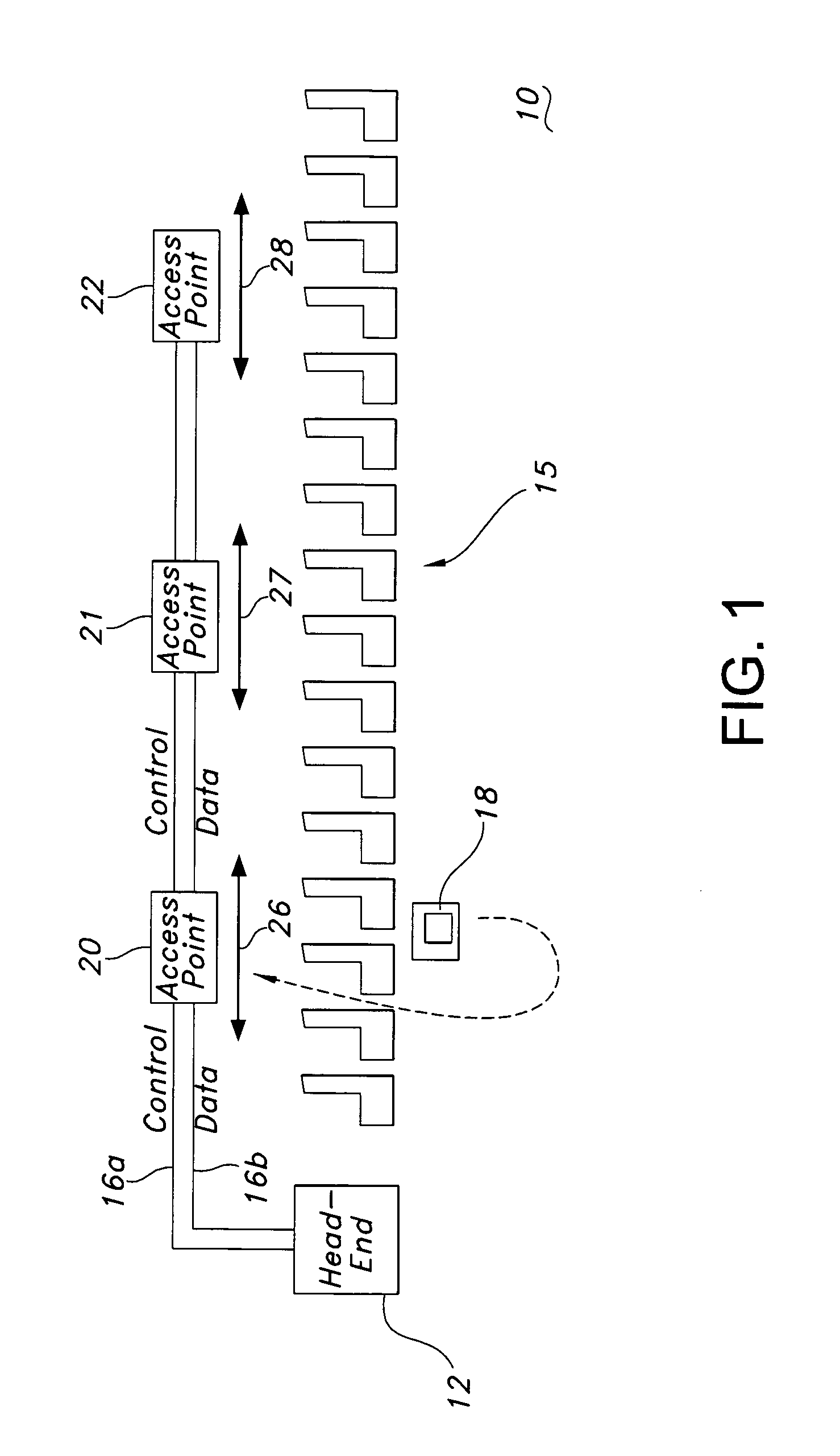
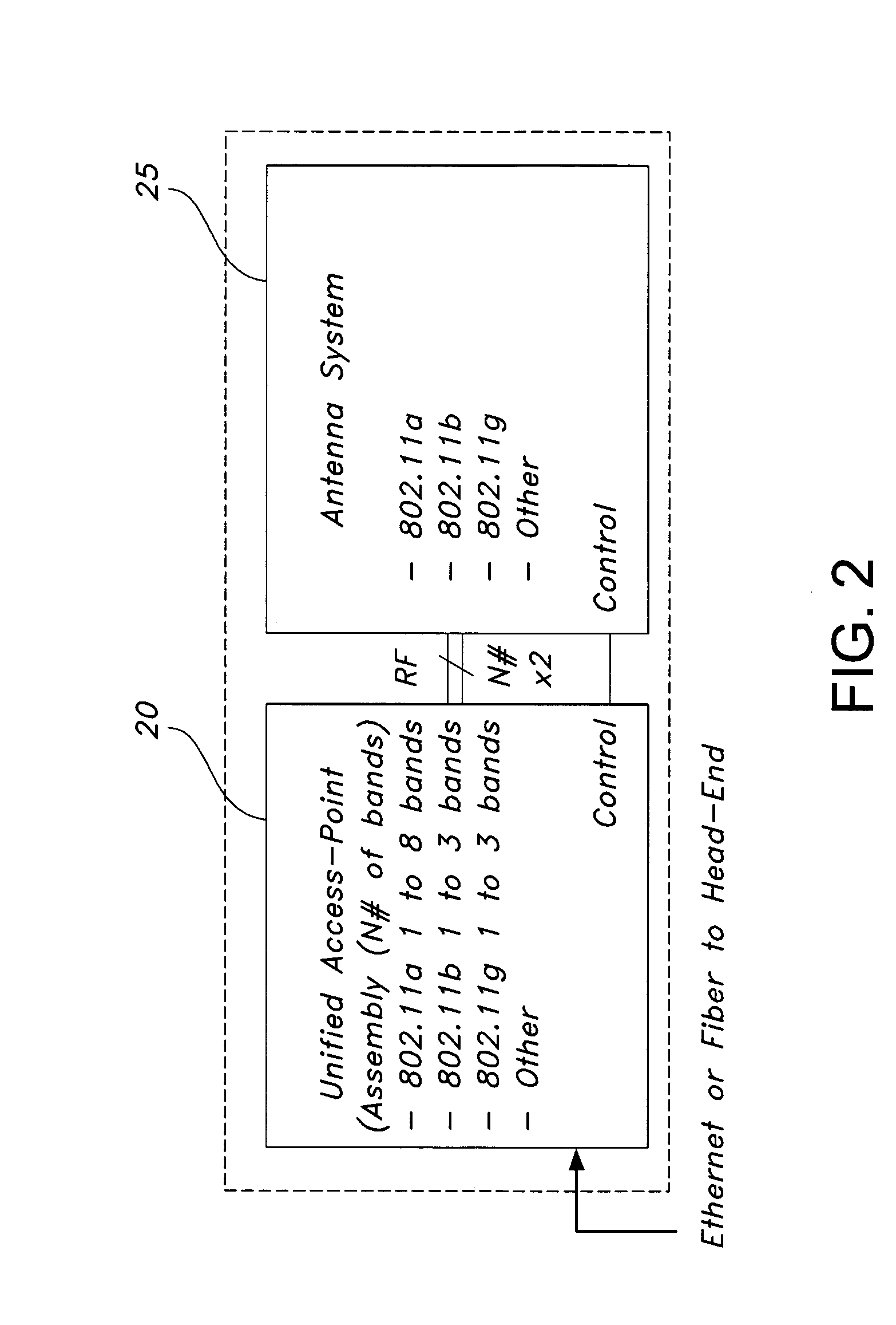
[0031]The invention described herein is for a wireless in-flight entertainment (IFE) and data distribution system comprising a configurable antenna system and a placement process for locating the configurable antenna system in an aircraft in such locations as cabin and flight deck areas. The present invention enables placement and calibration of a plurality of separate antenna beams and frequency bands from each aircraft mounted antenna system and access point thereby minimizing the amount of aircraft hardware and mitigating interference from adjacent antenna systems and access points reusing the same RF bands or sub-bands while maximizing connectivity performance to each seat client within the aircraft. The present invention serves to reduce installation time of antenna systems and wireless access points within the aircraft.

[0032]FIG. 1 is a simplified block diagram of a wireless IFE distribution system 10 where the present invention for the configurable antenna system and method f...


PUM


Abstract

A method of delivering programming to passenger seats with a wireless in-flight entertainment system in an aircraft cabin uses a configurable cabin antenna system. Control data and programming is delivered with a head end server and received with one or more access points connected to the head end server. One or more antenna systems, connected to the access points, are disposed at optimum selected locations in the aircraft cabin to provide the programming to the passengers. One or more personal electronic devices (PEDs) located receive the programming from the one or more configurable antennas. Beams of the one or more antenna systems are adjusted to deliver programming to the one or more PEDs at a required bit error rate.

Description

CROSS REFERENCE TO RELATED APPLICATIONS[0001]The present application is related to co-pending application Ser. No. 10 / 442,480 filed on May 21, 2003 entitled “Method and Apparatus for High Availability Passenger Entertainment Content Delivery” by James P. Mitchell. The co-pending application is assigned to the assignee of the present invention.BACKGROUND OF THE INVENTION[0002]The present invention relates to in-flight entertainment (IFE) systems and specifically to a wireless IFE distribution system with a configurable antenna system and a method of placement of the configurable antenna system within an aircraft cabin.[0003]In-flight entertainment systems have been installed on commercial airliners for a number of years. An in-flight entertainment system typically comprises the components necessary to present entertainment content to an airline passenger while in flight. Current IFE systems are wired systems that deliver programming to passengers similar to a cable television system....

Claims


Application Information

Patent Timeline
Patent Type & Authority Patents(United States)
IPC IPC(8): H04N7/18
CPCH04L67/12H04W16/28
Inventor MITCHELL, JAMES P.SAKARYA, FATMA AYHAN
Owner ROCKWELL COLLINS INC
Why Eureka
Try Eureka