[0058]The silicon comprising elongate elements and particles may include a coating, preferably a coating made with carbon, such as amorphous carbon, graphite, electroactive hard carbon, conductive carbon, carbon based polymers or carbon black. Coats are typically applied to the silicon structures to a thickness of between 5 and 40% by weight of the coated silicon structure. Methods of coating silicon particles and elongate elements are known to a person skilled in the art and include chemical vapour deposition, pyrolysis and mechanofusion techniques. Carbon coating of silicon structures through the use of Chemical Vapour Deposition techniques is disclosed in US 2009 / 0239151 and US 2007 / 0212538. Pyrolysis methods are disclosed in WO 2005 / 011030, JP 2008 / 186732, CN 101442124 and JP 04035760. Carbon coatings are able to assist in controlling the formation and stability of SEI layers on the surface of the anode. As indicated above coatings other than carbon based coatings can be used. Examples of suitable alternative coatings include compounds such as lithium fluoride or lithium salts of cyclic organic carbonate species or suitable metals such as aluminium, copper, gold and tin as well as conductive ceramic materials. Lithium based coatings can be obtained by reacting silicon with a solution of LiF or exposing silicon to a solution comprising a mixture of lithium ions and a cyclic or acyclic carbonate.
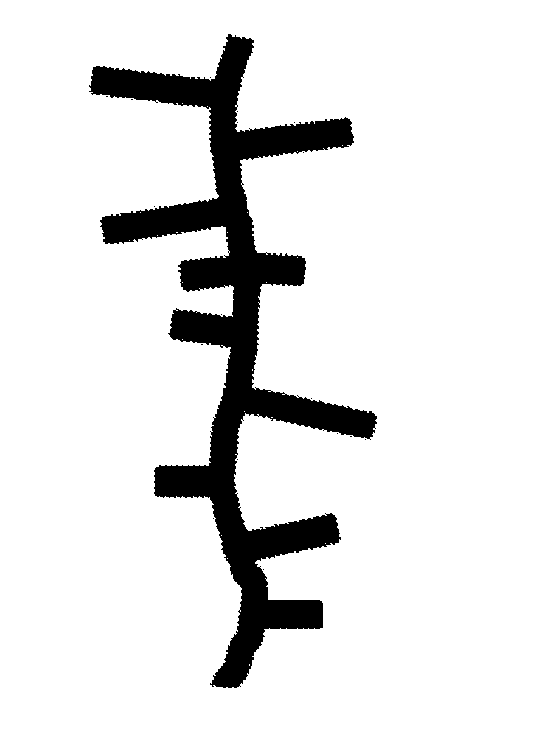
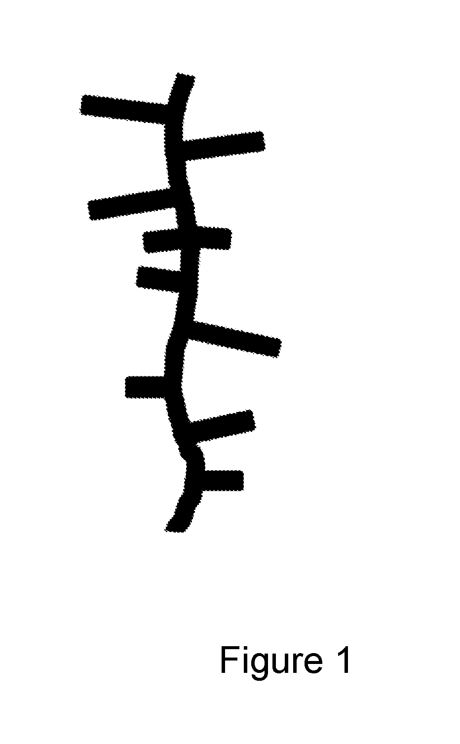
[0061]Compositions comprising fibres and / or ribbons as elongate elements and pillared particles are preferred because this provides the most efficient connectivity between the silicon comprising components of the electroactive material of the first aspect of the invention, whilst minimising the stresses that occur as a result of the volume changes that occur during the charging phase of the battery cycle. Native particles and / or porous particles may also be preferably added to the composition, since this has been found to improve the homogeneity of the composition. A fourth embodiment of the first aspect of the invention therefore provides a composition in which the silicon comprising component comprises one or more components selected from the group silicon comprising fibres, silicon comprising ribbons, pillared particles and optionally native particles and / or porous particles. The pillared particles preferably have a dimension in the range 5 to 35 μm and comprise pillars having a width in the range 80 nm to 250 nm and a length in the range 0.5 to 5 μm. The elongate elements preferably have a diameter in the range 80 to 250 nm and a length in the range 0.8 to 100 μm. The native particles, where present, preferably have a diameter in the range 1 to 8 μm with a D50 of 4 μm. Without wishing to be constrained by theory, it is believed that the selection of pillared particles characterised by the dimensions given ensures that the particles tend to occupy the voids or pores created by the entanglement of the fibres or ribbons upon formation of the felt structure rather than contribute to the creation of additional pores or voids. The entanglement of the particle pillars with the fibres or ribbons of the mat ensures that the particles are retained within the felt structure during the charge and discharge phase of the battery, which maximises the connectivity between the silicon comprising components of the electroactive material per se and also between the silicon comprising components and any other conductive materials present therein, thereby improving the capacity of an anode prepared using the material according to the first aspect of the invention. Further, because the elongate elements and the particles are retained within the structure through entanglement rather than through close packing of particles, there is sufficient space to accommodate the inherent volume changes of the material that occur during the charging and discharging phases of a battery cell, for example. This entangled structure therefore improves both the capacity and cycle-ability of a material including this structure and hence its long term performance. Further, because the silicon structures used in the manufacture of the electrode or anode materials according to the invention are themselves relatively easy and inexpensive to produce, the associated costs of fabricating anodes or electrodes from such materials is consequently low.
[0066]The binder is a component used to bind the components of the anode mix together either upon formation of the felt like mat or on application of the components to the current collector. The binder helps to maintain the integrity of the anode mix when used in battery cells. It also functions to help the anode mix adhere to the current collector. The binder can be added in an amount of 0 to 30%, preferably 6 to 20%, more preferably 6 to 14% and especially 12% by weight based on the weight of the anode mix. Examples of binders include, but are not limited to, polyvinylidene fluoride, polyacrylic acid, modified polyacrylic acid, carboxymethylcellulose, modified carboxymethylcellulose, polyvinyl alcohol, fluorocopolymers such as copolymers of hexafluoroethylene, polyimide, polyacrylic acid, styrene butadiene rubber and thermo or photopolymerizable materials including, but not limited to, monomers, oligomers and low molecular weight polymers and mixtures thereof which are polymerizable by light irradiation and / or heat treatment. Examples of polymerizable monomers include epoxy, urethane, acrylate, silicon and hydroxyl based monomers and acrylic derivatives which may be used alone or in combination. Polymerisation of these materials is initiated with light irradiation or heat treatment. The polymerizable oligomer is a polymerisation product of from 2 to 25 monomers and may be formed into polymers having a higher degree of polymerisation by light irradiation or heat treatment. The term polymerizable low molecular weight polymer includes linear polymers and cross-linked polymers having a low degree of polymerisation or a low viscosity. Examples of such polymers include polyester acrylate, epoxy acrylate, urethane acrylate and polyurethane.
[0067]Preferably the binder is selected from one or more of a polyacrylic acid, a modified polyacrylic acid or alkali metal salts thereof. Lithium and sodium salts are preferred. Suitably the polyacrylic acid binder has a molecular weight in the range 150,000 to 700,000, preferably 250,000 to 550,000, especially 450,000. Polyacrylic acid binders and sodium polyacrylic acid binders are able to bind to silicon materials containing impurities and are an ionically conductive component within the assembled cell. Suitably the silicon materials used will have a silicon purity of 90% to 99.999%, preferably 90% to 99.99%, more preferably 90% to 99.95% and especially 95% to 99.95% and will include high purity silicon used in the manufacture of semi-conductors as well as metallurgical grade silicon such as the Silgrain® material produced by Elkem of Norway. Silicon materials having a purity of less than 99.95% may be advantageous because these materials can be cheaper and the impurities can improve conductivity. However if the level of impurities is too high the performance of the active material in the cell can be reduced and a purity in the range 90% to 99.95% is preferred, for example, 95% to 99.9%. It will be appreciated therefore, that the silicon comprising elongate elements, particles and other silicon comprising components used in the preparation of compositions according to the first aspect of the invention may be derived from metallurgical grade silicon which can reduce the materials cost compared to compositions containing higher purity grades of silicon. Batteries including electrodes containing compositions of the first aspect of the invention, which include a binder comprising polyacrylic acid, a modified polyacrylic acid or an alkali salt thereof exhibit a significant reduction in first cycle loss and longer cycling.
[0076]The composition of the first aspect of the invention can be easily manufactured and a second aspect of the invention provides a method of preparing an electroactive material according to the first aspect of the invention, the method comprising the steps of mixing a) a plurality of metal or semi-metal comprising elongate elements selected from one or more of the group comprising fibres, tubes, threads, ribbons and flakes with b) a plurality of metal or semi-metal comprising particles selected from one or more of the group comprising pillared particles, porous particles and porous particle fragments.

