Co-axial multi-stage pulse tube for helium recondensation

a multi-stage, pulse tube technology, applied in the direction of container filling under pressure, domestic cooling apparatus, lighting and heating apparatus, etc., can solve problems such as thermal losses, and achieve the effects of eliminating convection losses, minimizing thermal losses, and minimizing convection losses

Inactive Publication Date: 2009-03-03
SUMITOMO HEAVY IND LTD +1
View PDF20 Cites 7 Cited by
  • Summary
  • Abstract
  • Description
  • Claims
  • Application Information

AI Technical Summary

Benefits of technology

[0020]A conventional two-stage pulse tube refrigerator has the pulse tubes and regenerators in separate parallel tubes. When mounted in the neck tube of a MRI cryostat the helium in the neck tube results in thermal losses due to convection because of the temperature differences between the pulse tubes and the regenerators. This invention discloses a novel way to eliminate the convection loss by having the regenerator be co-axial in the annular space around the pulse tube. At least the 2nd stage is co-axial but preferably, both stages are co-axial with the second stage pulse tube being central and the first stage pulse tube occupying the annular space between the second stage pulse tube and the first stage regenerator. Means to minimize thermal losses between the pulse tubes and regenerators are also disclosed.
[0021]The present invention eliminates the convection losses associated with different temperature profiles in the pulse tubes and regenerators by using a two-stage pulse tube having at least one stage being co-axial with novel means to minimize the thermal losses between the pulse tubes and regenerators. While the main application is envisioned to be the recondensing of helium in a MRI cryostat by a two-stage GM type pulse tube it can also be applied to recondensing hydrogen and neon in cryostats that are designed for High Temperature Superconducting, HTS, magnets. At the higher temperatures it is also practical to have the pulse tube be connected directly to a compressor and operate in a Stirling cycle mode at a much higher speed.

Problems solved by technology

When mounted in the neck tube of a MRI cryostat the helium in the neck tube results in thermal losses due to convection because of the temperature differences between the pulse tubes and the regenerators.

Method used


Image

  • Co-axial multi-stage pulse tube for helium recondensation
  • Co-axial multi-stage pulse tube for helium recondensation
  • Co-axial multi-stage pulse tube for helium recondensation

Examples


Embodiment Construction

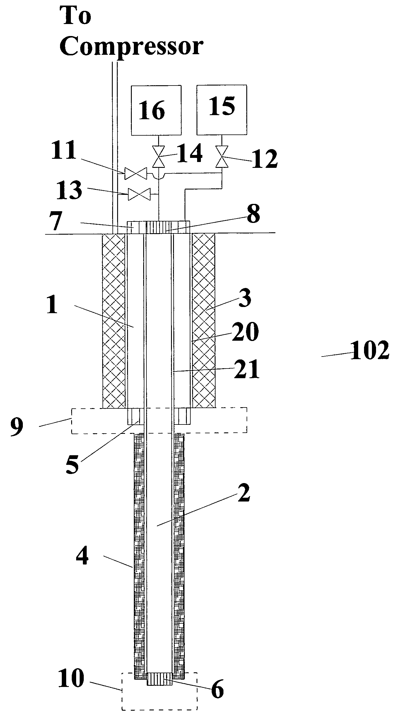
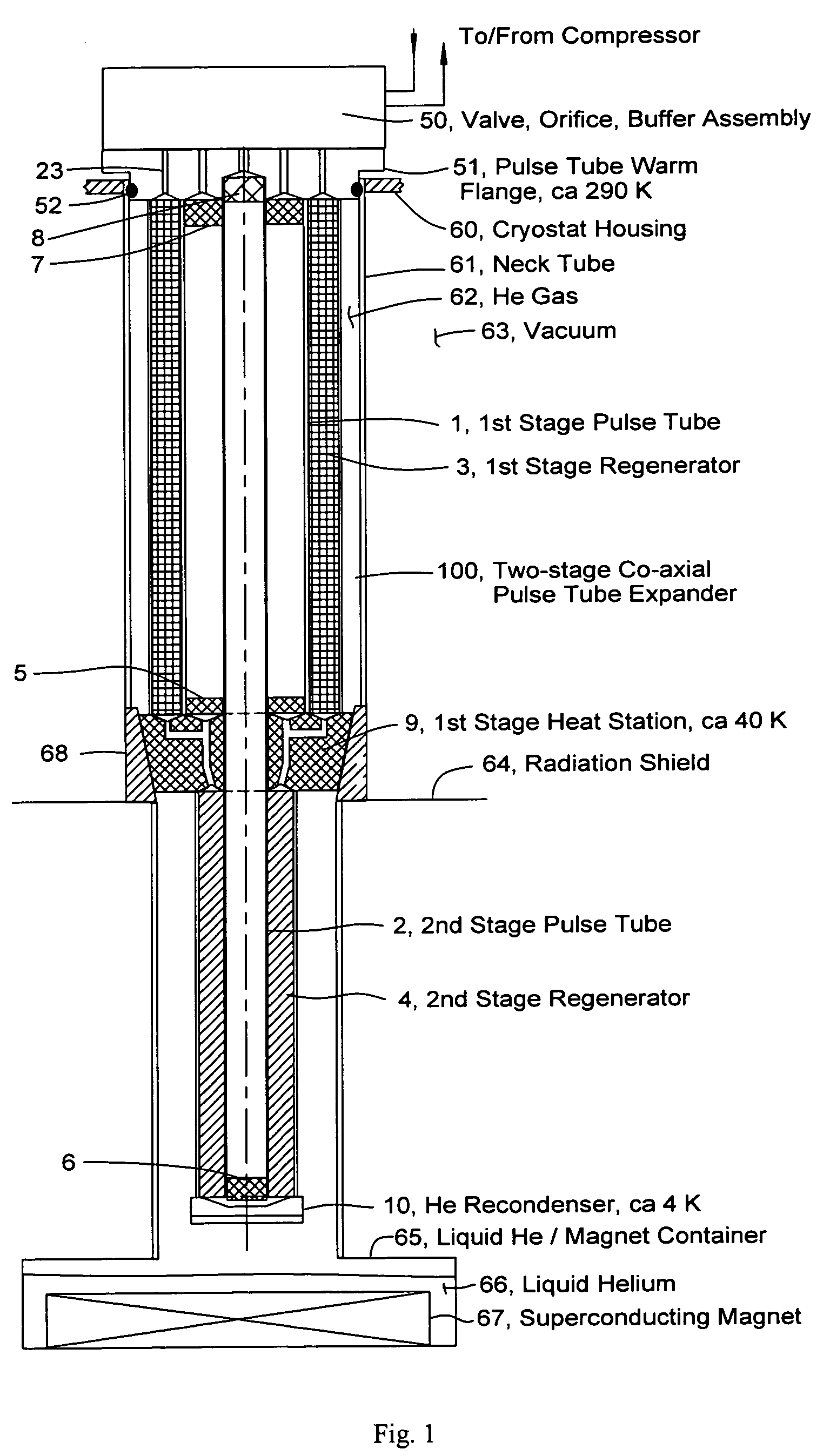
[0029]This invention provides a means to minimize thermal losses where a two-stage pulse tube is mounted in the neck tube of a liquid helium cooled MRI magnet. As shown in FIG. 1 a co-axial pulse tube is inserted in the neck tube where it is surrounded by gaseous helium that has a temperature gradient from room temperature, about 290 K, at the top to 4 K at the bottom. The pulse tube expander has a first stage heat station at about 40 K that is used to cool a shield in the magnet cryostat and a helium recondenser at the second stage.

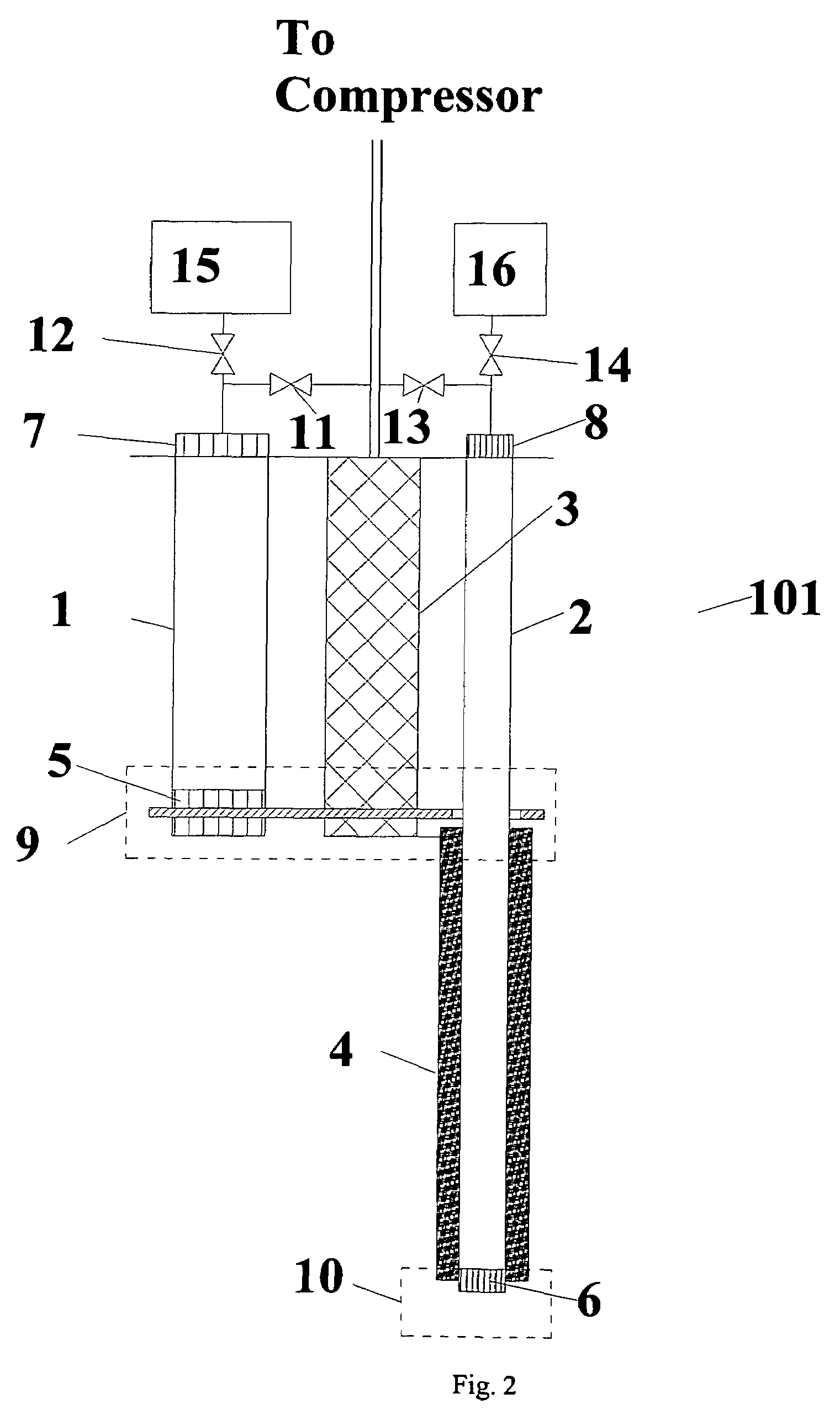
[0030]Having the pulse tube expander in the neck tube provides an easy way to remove it for service. The co-axial design is more compact than the conventional parallel tube design thus the neck tube can have a smaller diameter, and convective losses due to heat transfer between the pulse tubes and regenerators are eliminated.

[0031]Referring to FIG. 1, the MRI cryostat consists of an outer housing 60 that is connected to inner vessel 65 by neck tube 61. V...


PUM


Abstract

A two-stage pulse tube refrigerator having a compact design, low vibration and low heat loss is provided where at least the 2nd stage is co-axial but preferably, both stages are co-axial with the second stage pulse tube being central and the first stage pulse tube occupying the annular space between the second stage pulse tube and the first stage regenerator. Convection losses associated with different temperature profiles in the pulse tubes and regenerators are minimized by shifting the thermal patterns in the pulse tubes relative to the regenerators by one or more of spacers in the regenerators, physical differences in length with gas channel connections, adjustment of dc flow, and thermal bridges.

Description

CROSS REFERENCE TO RELATED APPLICATION[0001]This application claims priority from U.S. Provisional Application No. 60 / 641,199 filed Jan. 4, 2005, which is hereby incorporated by reference in its entirety.BACKGROUND OF THE INVENTION[0002]The present invention relates to multi-stage Gifford McMahon (GM) type pulse tube refrigerators as applied to recondensing helium in a MRI magnet. GM type refrigerators use compressors that supply gas at a nearly constant high pressure and receive gas at a nearly constant low pressure to an expander. The expander runs at a low speed relative to the compressor by virtue of a valve mechanism that alternately lets gas in and out of the expander. Gifford in U.S. Pat. No. 3,119,237 describes a version of a GM expander with a pneumatic drive. The GM cycle has proven to be the best means of producing a small amount of cooling below about 20 K because the expander can run at 1 to 2 Hz.[0003]A Pulse Tube refrigerator was first described by Gifford in U.S. Pat...

Claims


Application Information

Patent Timeline
Patent Type & Authority Patents(United States)
IPC IPC(8): F25B9/00
CPCF25B9/10F25B9/145F25B2309/1406F25B2309/1408F25B2309/1413F25B2309/1414F25B2309/1415F25B2309/1418F25B2309/14241F25B2309/1425F25B2400/17F25D19/006
Inventor XU, MINGYAOLONGSWORTH, RALPH
Owner SUMITOMO HEAVY IND LTD
Why Eureka
Try Eureka