Walker

a technology for walker and walker body, which is applied in the field of walking aids, can solve the problems of not being widely used, not being easy to operate by users, and complex structure, and achieves the effects of convenient processing and folding, light weight, and simple structure and assembly

Inactive Publication Date: 2009-03-03
GENTEEL HOMECARE PROD
View PDF4 Cites 14 Cited by
  • Summary
  • Abstract
  • Description
  • Claims
  • Application Information

AI Technical Summary

Benefits of technology

[0002]It is an object of the present invention to provide a walker with simple structure, which is easy for the user to operate and could be used widely.
[0004]The two leg extensions are assembled within the end sleeves on the two ends of the cross bar. A lock body is provided outside the end sleeve, and the lock body is fixed with the leg extension, and thus the lock body and the leg extension could rotate simultaneously with respect to the end sleeve. The block is connected to the lock body through the sub axis, the flange at the bottom of the block fits into the orientation hole of the end sleeve, and the bearing rod of the stretch part leans against the upper portion of the block above the axis hole, which forms the lever. When the walker is used, under the elastic force, the flange at the bottom of the block moves into the orientation hole, and thus the leg extension and the end sleeves are fixed together. When the walker is folded, with an inward push force acting on the block, the stretch part is strained, and the flange departs from the orientation hole on the end sleeve. The leg extension and the lock body can be rotated inside the end sleeves so as to fold the walker. The structure is simple, lightweight and easy to fold / unfold.
[0007]The bushing is provided with a glide slot on outer wall of the bottom, and a corresponding protrusion is provided on the top inner wall of the end sleeve. By fixing the protrusion with the glide slot, the rotation between the leg extension and cross brace can be limited during folding, which is easy for adjustment.
[0008]The top of the end sleeve is bugle-shaped, which is easy to allow the leg extension go through.
[0010]The leg extension is adjustable so as to adjust the height of the walker, which help more people with different height.
[0011]The invention of this walker is of the advantages including simple structure and assembly, easy processing and folding, light weight, convenient to transportation and storage. It meets the demands of different users.

Problems solved by technology

However, the structure is rather complex and not easy for the user to operate, and due to its high weight and price, it is to not as widely used as expectation.

Method used


Image

  • Walker
  • Walker
  • Walker

Examples


embodiment 1

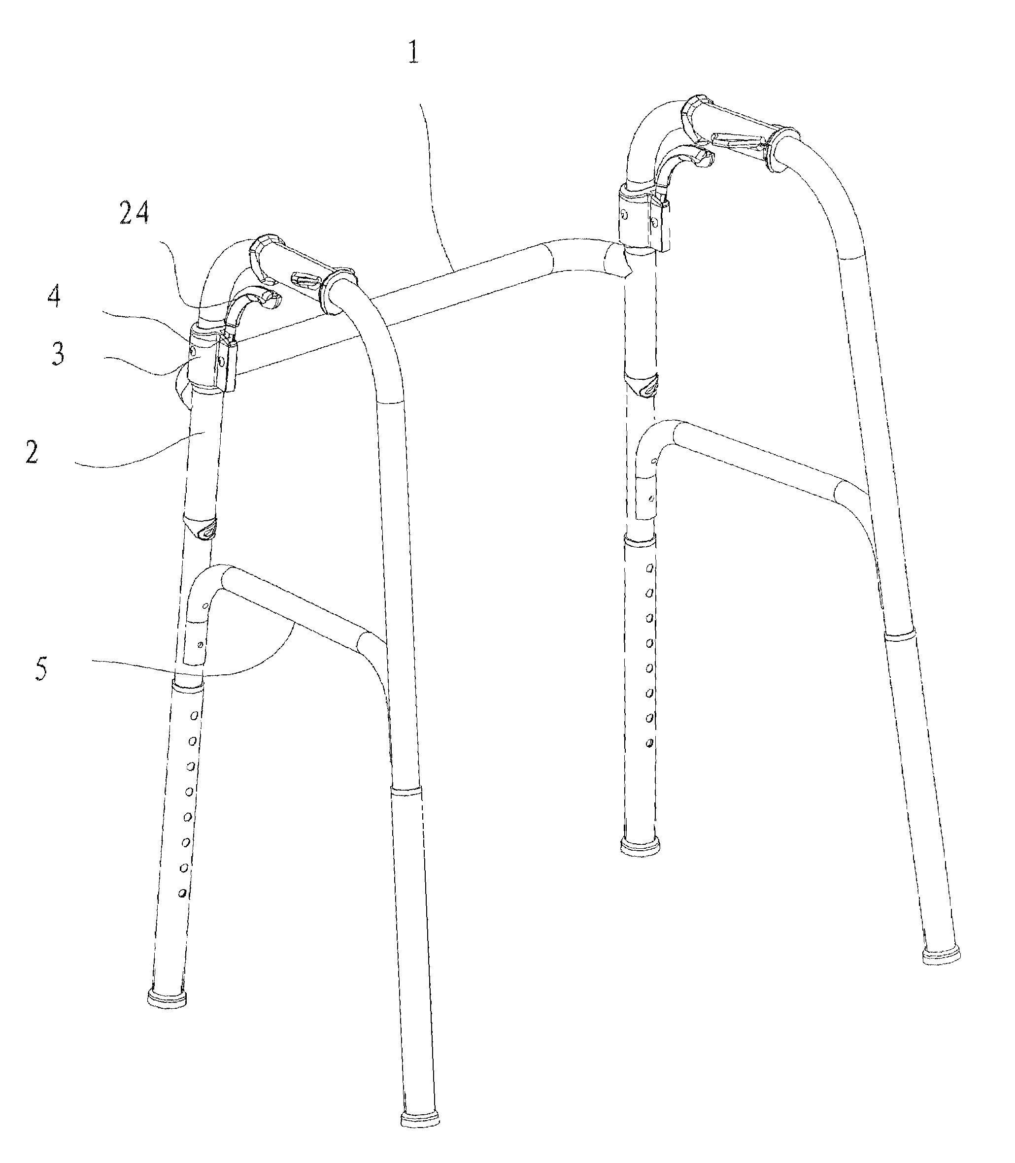
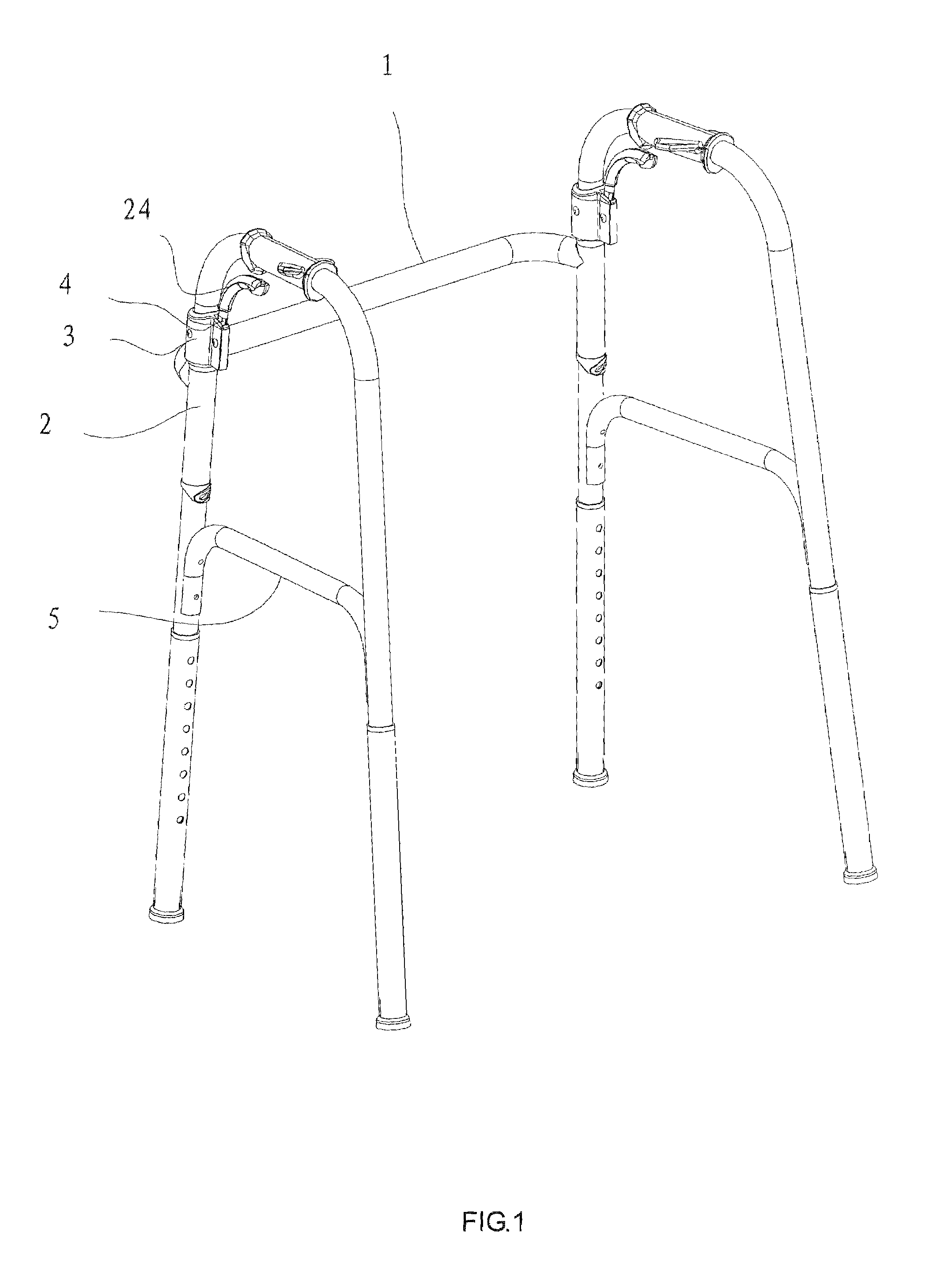
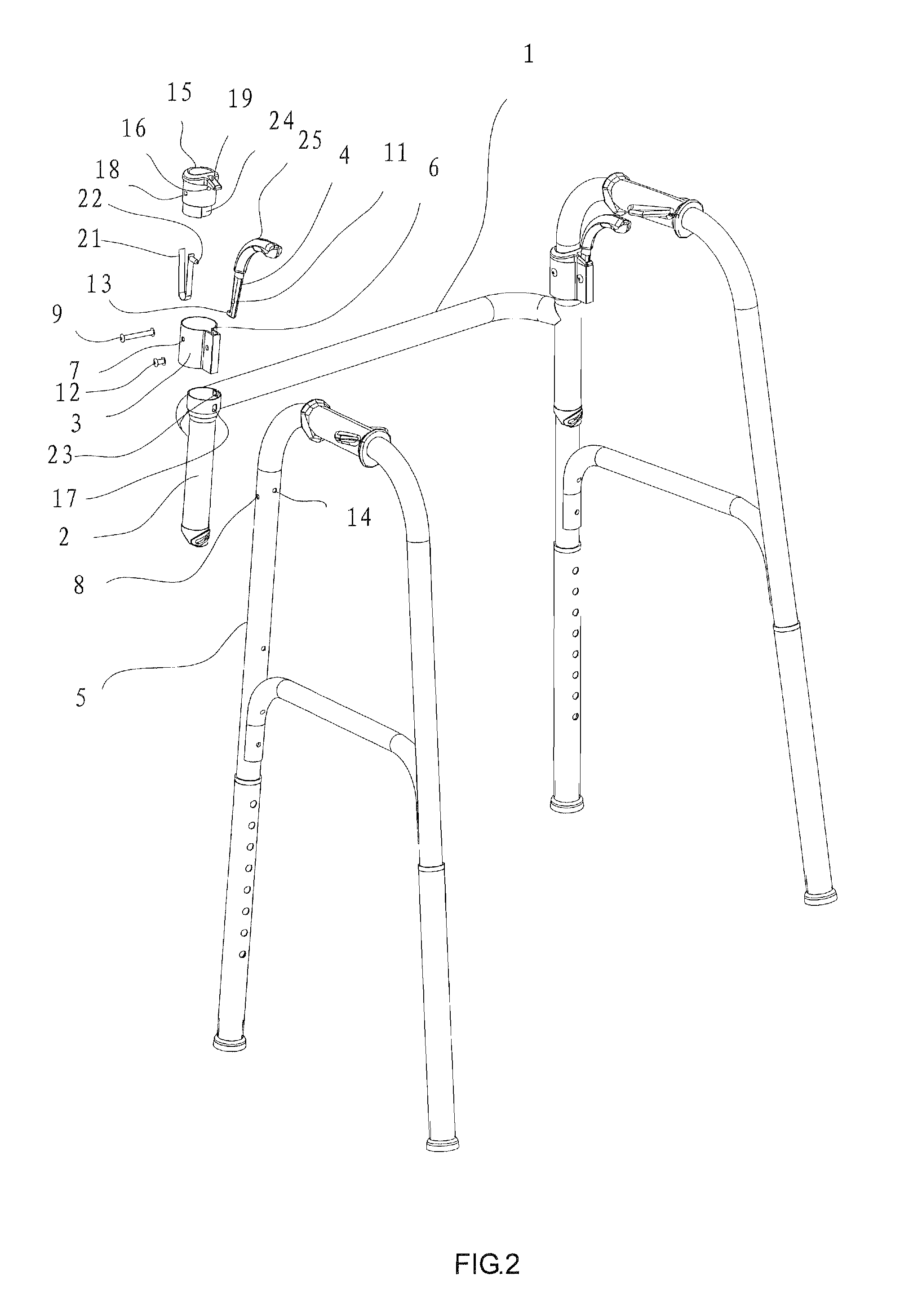
[0023]The walker, as shown in FIGS. 1, 2 and 3, includes an end sleeve 2 on each end of the cross brace 1, N-shaped leg extension 5, a lock body 3 having a housing 6 and a block 4 having an axis hole 11. The leg extension 5 is covered by the end sleeve 2. The lock body 3 is provided on top of the end sleeve 2. A pin hole 8 is provided on the leg extension 5. There is a corresponding connecting pin hole 7 on the lock body 3. A bushing 15 having an orientation pin hole 18 is provided between the leg extension 5 and the lock body 3. With the lock pin 9 going through the connecting pin hole 7, the orientation pin hole 18 and the pin hole 8, the lock body 3 and the bushing 15 are fixed on the leg extension 5. Referring to FIG. 4, the lock body 3 of the housing 6 has a hole for sub axis 10. Referring to FIG. 5, on top of bushing 15, a limit slot 19 through which the lock 4 can be inserted is provided. The block 4 is connected within the lock housing 6 by the sub axis 12 passing through th...

embodiment 2

[0028]Referring to FIG. 9, the walker includes an end sleeve 2 on both ends of the cross brace 1, N-shaped leg extensions 5, a lock body 3 having a housing 6 and a block 4 having an axis hole 11 on it. The leg extension 5 is covered by the end sleeve 2. The lock body 3 is provided on top of the end sleeve 2. A pin hole 8 is provided on the leg extension 5. There is a corresponding connecting pin hole 7 on the lock body 3. A bushing 15 having an orientation pin hole 18 is provided between the leg extension 5 and the lock body 3. With the lock pin 9 going through the connecting pin hole 7, the orientation pin hole 18 and the pin hole 8, the lock body 3 and the bushing 15 are fixed on the leg extension 5. The lock body 3 of the housing 6 has a hole for sub axis 10. On top of bushing 15, a limit slot 19 through which the lock 4 can be inserted is provided. The block 4 is connected within the lock housing 6 by the sub axis 12 passing through the hole for sub axis 10 and the axis hole 11....

embodiment 3

[0030]Referring to FIG. 10, the walker includes an end sleeve 2 on both ends of the cross brace 1, N-shaped leg extensions 5, a lock body 3 having a housing 6 and a block 4 having an axis hole 11. The leg extension 5 is covered by the end sleeve 2. The lock body 3 is provided on top of the end sleeves 2. A pin hole 8 is provided on the leg extension 5. There is a corresponding connecting pin hole 7 on the lock body 3. A bushing 15 having an orientation pin hole 18 is provided between the leg extension 5 and the lock body 3. With the lock pin 9 going through the connecting pin hole 7, the orientation pin hole 18 and the pin hole 8, the lock body 3 and the bushing 15 are fixed on the leg extension 5. The lock body 3 of the housing 6 has a hole for sub axis 10. On top of bushing 15, a limit slot 19 through which the lock 4 can be inserted is provided. The block 4 is connected within the lock housing 6 by the sub axis 12 passing through the hole for sub axis 10 and the axis hole 11. An ...


PUM


Abstract

A walker comprises: a cross brace having an end sleeve on each end, N-shaped leg extensions, a lock body having a housing and a block having an axis hole, wherein the leg extension is covered by the end sleeve, the lock body is provided on top of the end sleeve, the leg extension and the lock body are provided with a pin hole and a connecting pin hole respectively at corresponding positions and fixed by a lock pin, the housing of the lock body is provided with a hole for sub axis, the block is connected inside the housing by a sub axis passing through the hole for sub axis and the axis hole, the end sleeve is provided with an orientation hole, a flange for fitting with the orientation hole is provided at the bottom of the block in the housing, a stretch part with a bearing rod is provided inside the leg extension, and the bearing rod leans against the upper portion of the block above the axis hole by passing through a through hole on the leg extension. The invention of this walker is of simple structure and assembly, easy processing and folding, light weight, convenient to transportation and storage. It meets of the demands of different users.

Description

BACKGROUND OF THE INVENTION[0001]The present invention relates to a walking aid, more particularly to a locking mechanism for use in a frame walker. Frame walking aids has been used to help the disabled or the old with mobility to increase their independence, and it is of great importance to their life. Most of the walking aids are foldable and easy for transportation and storage. However, the structure is rather complex and not easy for the user to operate, and due to its high weight and price, it is to not as widely used as expectation.SUMMARY OF THE INVENTION[0002]It is an object of the present invention to provide a walker with simple structure, which is easy for the user to operate and could be used widely.[0003]The technical solution of the invention is as follows: a walker includes a cross brace having an end sleeve on each end, N-shaped leg extensions, a lock body having a housing and a block having an axis hole. The leg extension is covered by the end sleeve. The lock body ...

Claims


Application Information

Patent Timeline
Patent Type & Authority Patents(United States)
IPC IPC(8): A45B9/02A61H3/00
CPCA61H3/00A61H2201/0161
Inventor LI, QINFENGLIANG, SAM
Owner GENTEEL HOMECARE PROD
Why Eureka
Try Eureka