Drive engagement apparatus

a technology of engagement apparatus and drive shaft, which is applied in the direction of friction clutches, non-mechanical actuated clutches, automatic clutches, etc., can solve the problems of clutch failure, friction plate slippage and overheating, and large load inertia,

Inactive Publication Date: 2009-03-03
ARTHUR KNOWLES
View PDF7 Cites 3 Cited by
  • Summary
  • Abstract
  • Description
  • Claims
  • Application Information

AI Technical Summary

Benefits of technology

[0007]The present invention seeks to ameliorate at least some of the problems associated with known clutches. In particular, the clutch according to the present invention includes a piston valve which allows the configuration of the clutch to be altered so that it may be capable of overcoming the inertia of large loads.
[0008]At its most general, the present invention separates the functions of (i) engaging a driving member with a driven member, and (ii) activating a friction drive e.g. by pushing friction plates together, by incorporating a valve arrangement in the piston which allows a force to act through the piston without necessarily moving the driving member. Thus, these actions are separated without necessarily increasing the size of the housing or necessarily requiring further power supplies or input ports. As a result, the present invention provides a way of activating the friction drive with a larger force than before by using a actuator having a larger area, yet still being able to provide the system in a housing that is no larger than known housings. Furthermore, the clutch of the present invention is only used to synchronise the driving and driven members, thus it is less likely to burn out through overloading. The valve arrangement in the piston also allows an air controlled friction drive to be deactivated just before the moment of positive engagement of the clutch, so that engagement proceeds smoothly.
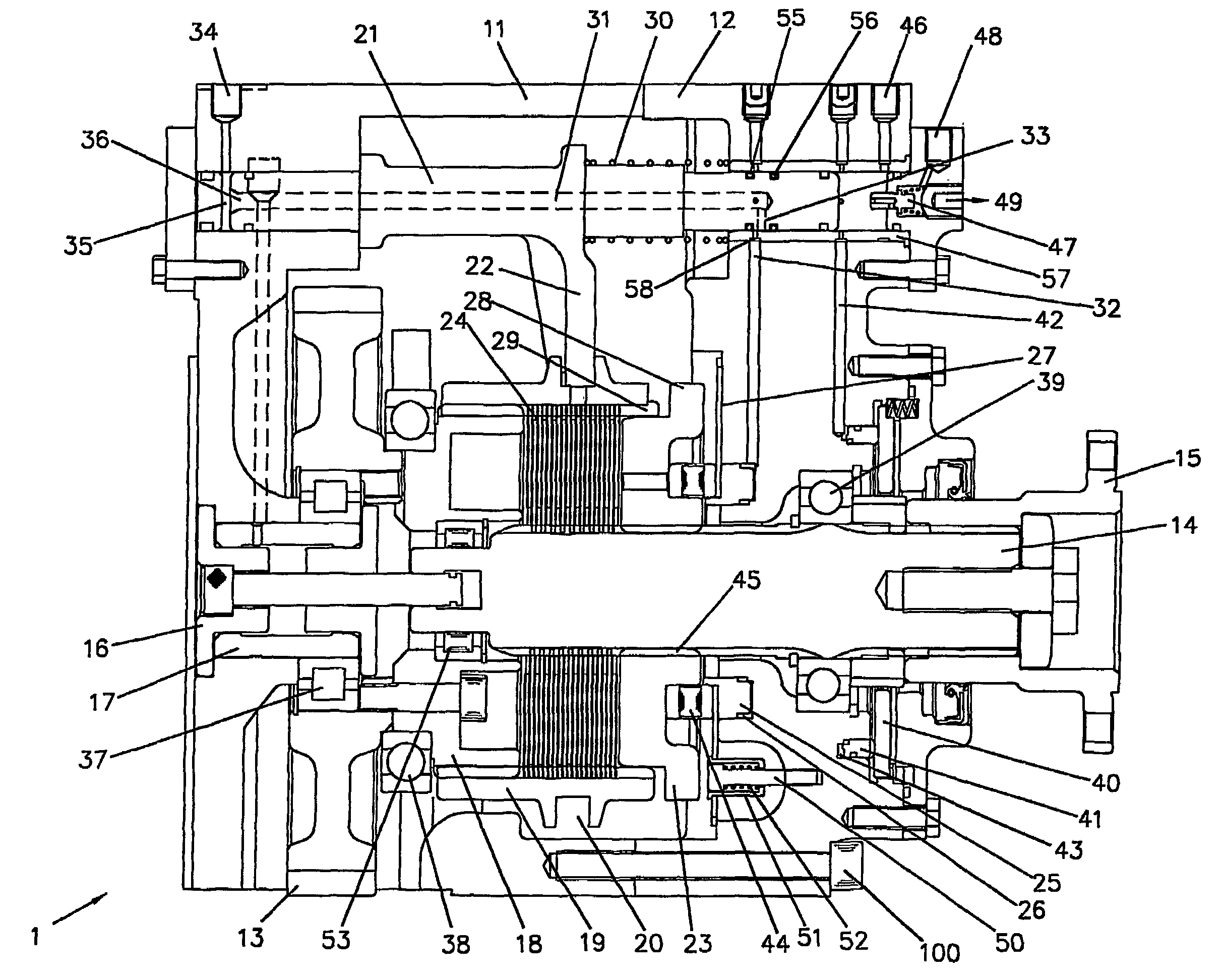
[0017]Preferably, sealing means are located around the piston at a predetermined axial distance from each side of the radial hole, the sealing means defining a zone in which pressure from the passageway acts. Preferably, the sealing means are sealing rings positioned around the piston. The sealing rings are preferably positioned such that the zone is isolated from the compressed air communication means when the piston has moved the first rotatable member a predetermined distance towards engagement with the second rotatable member. Thus, one of the sealing rings may move over the bore in the housing as the first rotatable member moves into engagement with the second rotatable member, thereby releasing pressure from the cylinder. The piston may include a race to release air into the housing space when the zone is isolated from the bore in the housing. Preferably, therefore, the pressure ceases to act on the friction drive actuator just before or at the same time as positive engagement is established between the first and second rotatable members. Thus, the apparatus may disengage the friction drive just before or at the same time as positive engagement is established between the rotary driving member and the driven member. This is achieved by selecting the positions of the sealing means carefully so that the friction drive actuator is isolated from the pressure acting on it at the relevant moment, e.g. when the first rotatable member begins to slide into full engagement with the second rotatable member. Thus, at the point of direct mechanical connection, the clutch will be free from any load contact, so any load or speed fluctuations at that point will not affect the clutch.
[0019]Preferably, the friction drive actuator includes an annular pressure ring slidably mounted in the housing. The area of the annular pressure ring on which the pressure acts may be greater than the area of the piston on which pressure acts. There is less restriction on space in the opposite side of the housing from the driving member, therefore the actuator may be larger. The advantage of having a large actuator is that e.g. compressed air can act on a larger area than e.g. the end of the pneumatic ram (which was the area acted on in known clutches). Thus, a larger force for a given pressure can be obtained.

Problems solved by technology

Obviously, a larger load has more inertia and is harder to start rotating.
If demand on the clutch is raised beyond its capacity, the friction plates are likely to slip and overheat; the clutch will eventually fail by burning out.
A large torque is required to start the rotation because of the inertia of the load attached to the output shaft.
Since the size of the ram is limited e.g. by the constraints of the size of the housing itself, the amount of force that can be generated is also limited.
Furthermore, when large loads need to be started, the bending moment on the fork element deflects the line-ability of the clutch housing.
As a result, the pneumatic ram is pulled out of alignment with the housing, which can wear the components.

Method used


Image

  • Drive engagement apparatus
  • Drive engagement apparatus
  • Drive engagement apparatus

Examples


first embodiment

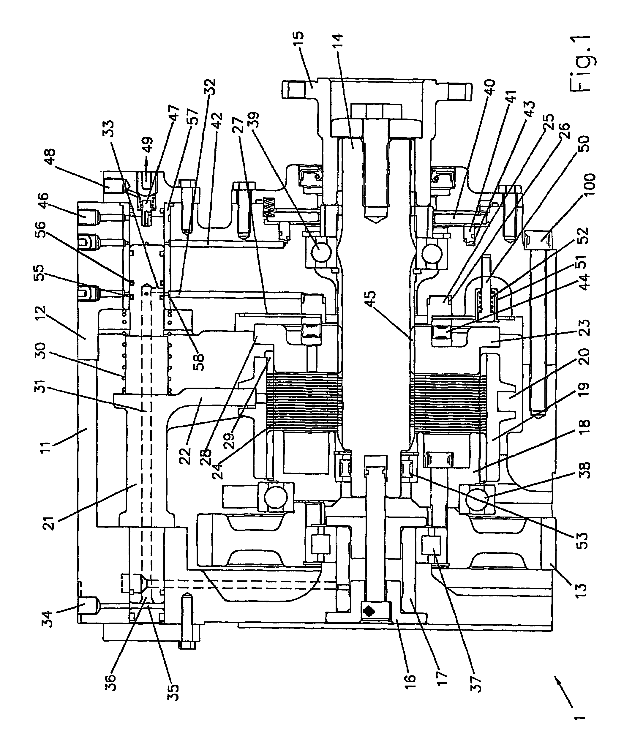
[0034]the drive arrangement 1 of the invention shown in FIG. 1 has a housing consisting of two parts 11, 12 fixed together using e.g. bolt 100. The housing defines a space in which the mechanism of the invention is located. A driving gear 13 is rotatably mounted in the housing by means of roller bearing 37, which is located on shaft 17 fixed to stub 16 on the end wall of the housing. Driving gear 13 is externally splined to be permanently engaged to a rotating member (not shown) of an engine. Thus, when the engine is running, driving gear 13 rotates. Extension member 18 is bolted to driving gear 13 to rotate with it. Extension member 18 is splined around its external surface. Driving sleeve 19 is internally splined, and is keyed into axially slidable engagement with the extension member 18, so that it rotates with the driving gear 13 but is axially slidable relative to the extension member 18.

[0035]The housing also holds output shaft 14 via roller bearing 39. One end of the output s...

second embodiment

[0051]FIG. 4 shows a drive arrangement 2 which is the invention. It has many components in common with the arrangement shown in FIG. 1, and these components are labeled with the same reference number.

[0052]The drive arrangement shown in FIG. 4 is for smaller loads than the arrangement shown in FIG. 1. In FIG. 1, the axis of rotation of the output shaft 14 was aligned with the drive axis (i.e. the axis of rotation of the driving gear 13). In FIG. 4, the axis of rotation of the output shaft 14 makes an angle with drive axis.

[0053]Furthermore, the direction of the sleeve's 19 slide into engagement with the output dog 23 with opposite to that of the arrangement shown in FIG. 1. In FIG. 4, the sleeve 19 slides away from the element to be driven (not shown) which is attached to the output shaft 14 by the coupling 15. Thus, the piston arrangement is reversed with respect to the output shaft. The space 35 for receiving input compressed gas to move the piston 21 is now in the same housing pa...

third embodiment

[0058]FIG. 5a shows a drive arrangement 3 which is the invention. Like FIG. 1, the drive arrangement 3 shown in FIG. 5a is of the type where the rotation axis of the shaft 14 is aligned with the rotation axis of the driving gear 13. One difference between the drive arrangements of FIGS. 1 and 5a is the direction of axial movement of the sleeve to effect positive drive engagement. Unlike FIG. 1, in FIG. 5a, the sleeve 19 is not keyed into the extension member 18 and therefore does not rotate with the engine. Thus, when the drive arrangement 3 is in the disengaged position (shown in FIG. 5a), the sleeve 19 is at rest. This means that the friction plates 24 that are engaged with the sleeve are also at rest. In order to activate a friction drive, it is therefore necessary that the friction plates that are engaged with the shaft 14 rotate with the driving gear 13. To achieve this, the shaft 14 includes a driven part 64 that is drivably connected to and rotates with the extension member 1...


PUM


Abstract

A drive arrangement (1) is disclosed where a driving gear (13) is engageable with a shaft (14) by engaging an axially movable sleeve (19) with a dog (23). One of the sleeve (19) or dog (23) is drivably connected to the gear (13) and the other to the shaft (14). A piston (21) is engaged via fork (22) with the sleeve (19); axial movement of the piston (21) causes axial movement of the sleeve (19). A delay device is included which prevent engagement between the sleeve (19) and dog (23) until the rotational speeds of those elements is equalized. The delay device include a friction plates (24) which create a friction drive between the driving force (e.g. gear (13)) and the element to be driven. The friction drive is actuated by actuator (25) under the same compressed air supply that acts on piston (21). Torque acting between the friction plates (24) and sleeve (19) prevent the sleeve (19) from moving into engagement with the dog (23) before the speeds of the sleeve (19) and dog (23) have equalized.

Description

CROSS REFERENCE TO RELATED APPLICATIONS[0001]This is a U.S. national phase application under 35 U.S.C. § 371 of PCT International Patent Application No. PCT / GB2004 / 002496, filed 11Jun. 2004, which claims priority to GB 0313497.0, filed 11 Jun. 2003. PCT International Patent Application No. PCT / GB2004 / 002496 was published in English as WO 2004 / 109137 A1 on 16 Dec. 2004 under PCT Article 21(2).FIELD OF THE INVENTION[0002]The invention described herein relates to engagement devices for enabling a rotating driving member to be brought into smooth positive engagement with a load to be driven by e.g. synchronising the driving member with a driven member. For example, the invention could be used in a type of clutch to smoothly engage a driving member with e.g. heavy duty equipment fitted to vehicles, e.g. fire engine pumps, road marking equipment, blowers, vacuum tankers, dynamos etc.BACKGROUND TO THE INVENTION[0003]A known clutch arrangement includes friction plates enclosed in a clutch h...

Claims


Application Information

Patent Timeline
Patent Type & Authority Patents(United States)
IPC IPC(8): F16D23/04F16D25/08
CPCF16D23/04F16D2023/0643F16D2023/0693
Inventor KNOWLES, REGINALD
Owner ARTHUR KNOWLES
Why Eureka
Try Eureka