

Target fan starting method
A fan and target technology, which is applied in the electronic field, can solve problems such as insufficient, or when the rotor is in a certain position, the rotor has a large resistance to rotation, so as to improve the probability of successful startup, improve reliability, and reduce equipment maintenance costs.
- Summary
- Abstract
- Description
- Claims
- Application Information
AI Technical Summary
Problems solved by technology
Method used
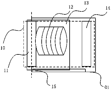
Image

Examples
Embodiment 1
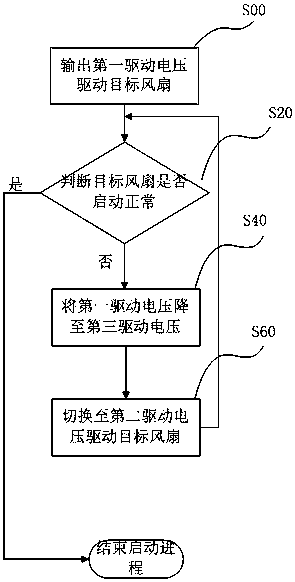
[0056] like figure 2 As shown, Embodiment 1 of the present invention provides a method for starting a fan, and the method includes:
[0057] Step S00: Outputting the first driving voltage to drive the target fan;
[0058] The fan has a minimum operating voltage during normal operation, that is, an operating voltage that maintains the lowest rotational speed, such as 5V, a maximum rated operating voltage, that is, an operating voltage that maintains the highest rotational speed, such as 12V, and a starting voltage that is used to start the fan. The first driving voltage is usually set as the starting voltage of the fan, which can be the minimum operating voltage or slightly higher than the minimum operating voltage, such as 6V, so that the fan coil can obtain current, and the magnetic force between the fan and the magnet can overcome the rotor. static friction, so that the rotor drives the fan blades to rotate.
[0059] Step S20: judging whether the target fan starts normall...
Embodiment 2
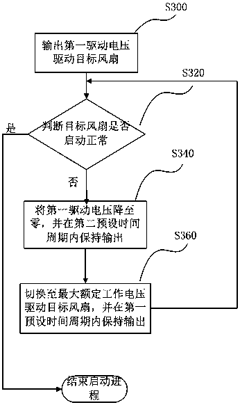
[0086] like image 3 As shown, the method for starting the fan provided by the embodiment of the present invention includes:
[0087] Step S300: Outputting the first driving voltage to drive the target fan;
[0088] Step S320: judging whether the target fan starts normally;
[0089] If it is judged that the startup is normal, the startup process is ended;
[0090] If it is judged that the startup is abnormal, execute:
[0091] Step S340: reducing the first driving voltage to zero, and maintaining the output within a second preset time period;
[0092] After the second preset time period ends,
[0093] Step S360: switch to the maximum rated operating voltage to drive the target fan, and maintain the output within the first preset time period;
[0094] Go to step S320.
[0095] Through the above control process, when it is judged that the target fan starts abnormally, first reduce the drive voltage of the target fan to the minimum, that is, zero volts, and then increase it...
Embodiment 3
[0098] Embodiment 3 of the present invention provides a method for starting a fan on the basis of Embodiment 1 or Embodiment 2, such as Figure 4 As shown, after judging that the startup is abnormal, step S430 is also included: judging whether the number of cycles of switching to the second driving voltage is greater than M,
[0099] If it is greater than M, stop starting the target fan and give an early warning;
[0100] If it is less than M, execute the next step, where M is an integer greater than or equal to 1.
[0101] In a specific implementation, M can be set to 2, or 3, or 5, which can be adjusted according to software design requirements. Therefore, after a limited number of attempts to start, if it is still unsuccessful, stop starting the fan, consider the fan to be faulty, and give an early warning.
[0102] In specific implementation, the second driving voltage can gradually increase with the change of the set number of cycles M, but it is always lower than the m...
PUM
 Abstract
Description
Claims
Application Information