
Universal mounting assembly

a universal mounting and assembly technology, applied in the field of brackets, can solve the problems of affecting the delivery of mail to the homeowner's door, affecting the appearance of the home, and the joint between the post and the arm is a significant failure point, so as to achieve compact and economical, economical transportation and display

Inactive Publication Date: 2009-03-03
LUTZKE DAVID E
View PDF18 Cites 10 Cited by
  • Summary
  • Abstract
  • Description
  • Claims
  • Application Information

AI Technical Summary

Benefits of technology

[0011]It is a further object of the present invention to provide a mounting assembly for mailboxes which can be economically fabricated of metal or plastic.
[0012]It is an additional object of the present invention to provide a box mounting assembly and a packaging assembly which is compact and economical.
[0013]It is another object of the present invention to provide a mounting assembly for mailboxes which can be nested compactly with other like assemblies for economical transport and display.

Problems solved by technology

More recently, efforts to obtain greater letter carrier efficiency have meant that mail deliveries to the homeowner's door have been curtailed for newer construction, making the roadside mailbox more prevalent in suburbia, and even in newer urban developments.
As a result of this stress, and the natural movement of wood as it expands and contracts, the joint between the post and the arm is a significant point of failure.
Even if the joint doesn't completely fail, over time the arm may become loose and sag.
As a result, mass produced kits are available, but often such assemblies can be lacking in a desired quality of fit and appearance.

Method used


Image

  • Universal mounting assembly
  • Universal mounting assembly
  • Universal mounting assembly

Examples


Embodiment Construction

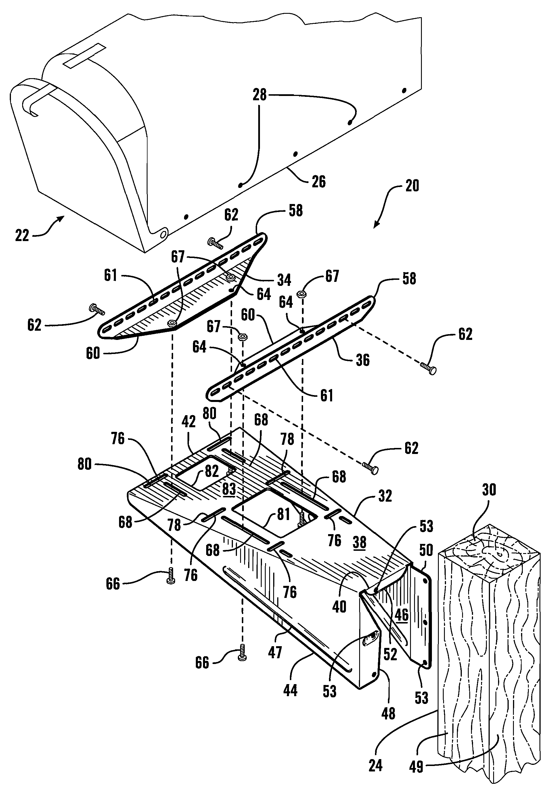
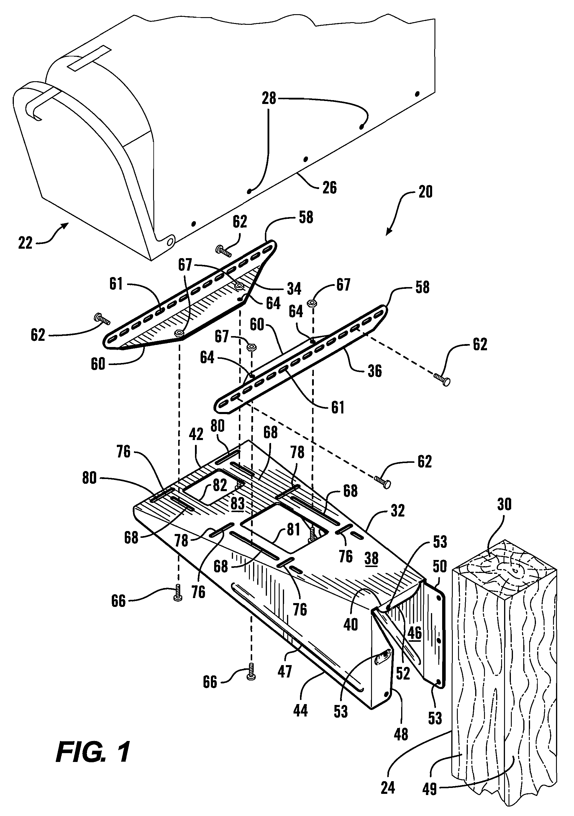
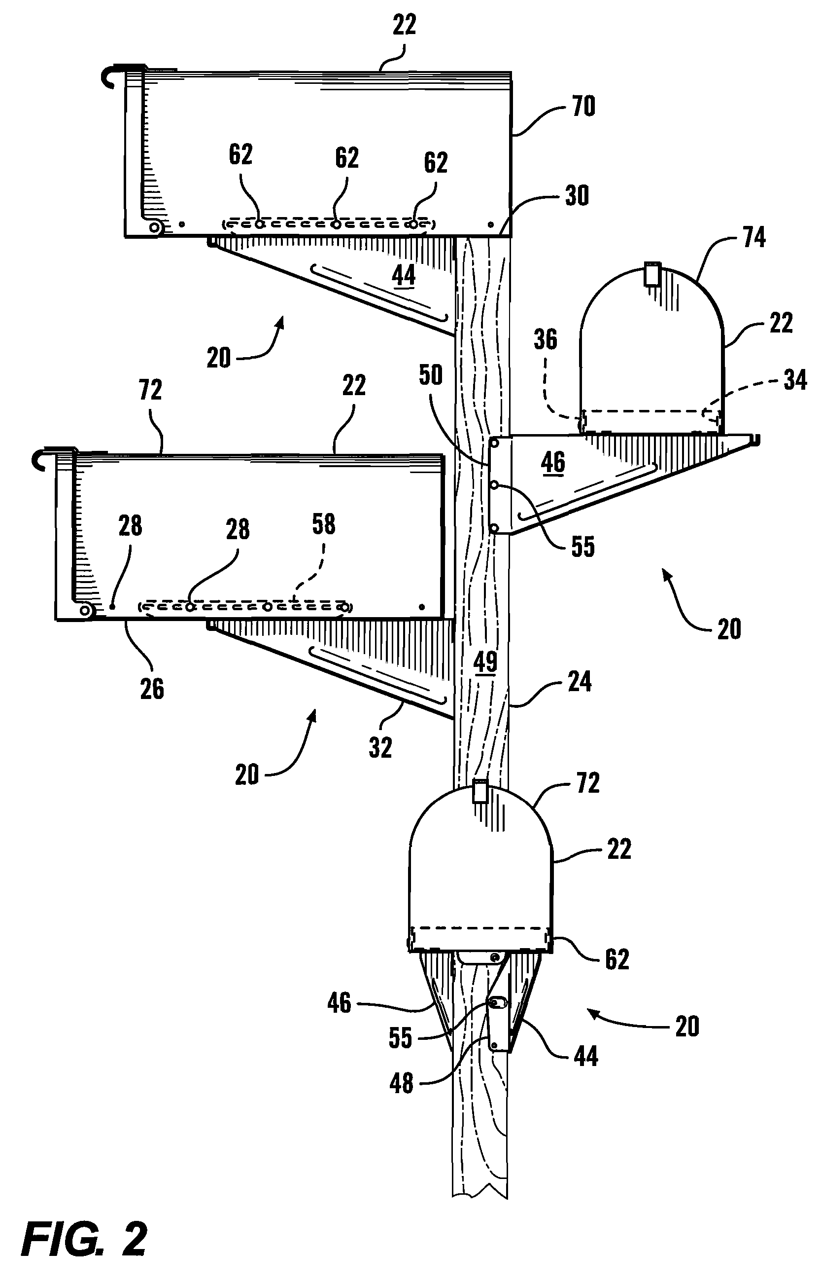
[0023]Referring more particularly to FIGS. 1-8, wherein like numbers refer to similar parts, a mailbox mounting assembly 20 is shown in FIGS. 1 and 2. The assembly 20 securely mounts a conventional mailbox 22 to a conventional wooden post 24. Mailboxes 22 are available in a variety of sizes and heights, but usually have downwardly projecting lips 26 which are provided with mounting holes 28 which extend sidewardly through the lips 26. The post 24 will typically be a treated dimensioned lumber member, with nominal dimensions of 4×4 inches (actual dimensions of about 3½ by 3½ inches), 4×6, or 6×6 inches. The post 24 has a lower end, not shown, which extends into the ground or is otherwise fastened, and an upper end 30 to which the mailbox 22 is attached by the mounting assembly 20.

[0024]The mailbox mounting assembly 20 has a single main bracket 32 to which a first top bracket 34 and a second top bracket 36 are positionably connected. As shown in FIG. 1, the main bracket 32 is formed o...


PUM


Abstract

A mailbox is mounted to two perpendicular faces of a post by a mounting assembly main bracket with two perpendicular flanges. The main bracket has a horizontal top wall from which two diverging sidewalls extend downwardly. The top wall has two sets of perpendicular slots, which receive two parallel right angle top brackets to receive the mailbox in a position either partially overlying the top of the post, projecting from the post, or offset from the post in a transverse orientation. Another embodiment has a main bracket with an integral top bracket, and only one adjustable top bracket. For sale, the top brackets mount to the main bracket by a label sheet wrapping the top wall and holding a fastener container.

Description

CROSS REFERENCES TO RELATED APPLICATIONS[0001]This application is a continuation-in-part of U.S. application Ser. No. 11 / 534,301, filed Sep. 22, 2006, now U.S. Pat. No. 7,185,803, which is a continuation-in-part of application Ser. No. 11 / 325,725, filed Jan. 5, 2006, now abandoned, the disclosures of both of which applications are incorporated by reference herein.STATEMENT AS TO RIGHTS TO INVENTIONS MADE UNDER FEDERALLY SPONSORED RESEARCH AND DEVELOPMENT[0002]Not applicable.BACKGROUND OF THE INVENTION[0003]The present invention relates to brackets in general, and to assemblies for connecting mailboxes to posts in particular.[0004]Stanchion mounted mailboxes have been associated with rural areas as postal carriers seldom travel the long, rugged driveways associated with farms or remote locations. More recently, efforts to obtain greater letter carrier efficiency have meant that mail deliveries to the homeowner's door have been curtailed for newer construction, making the roadside mai...

Claims


Application Information

Patent Timeline
Patent Type & Authority Patents(United States)
IPC IPC(8): A47G29/12
CPCA47G29/1216
Inventor LUTZKE, DAVID E.
Owner LUTZKE DAVID E
Learn More