
Semiconductor device having conductive adhesive layer and method of fabricating the same

a technology of conductive adhesive layer and semiconductor, which is applied in the direction of semiconductor devices, semiconductor/solid-state device details, electrical apparatus, etc., can solve the problems of increasing fabrication costs, deteriorating reliability of wire bonding, and difficult to employ in assembling and packaging processes, so as to achieve the effect of high reliability

Inactive Publication Date: 2007-12-27
SAMSUNG ELECTRONICS CO LTD
View PDF8 Cites 9 Cited by
  • Summary
  • Abstract
  • Description
  • Claims
  • Application Information

AI Technical Summary

Benefits of technology

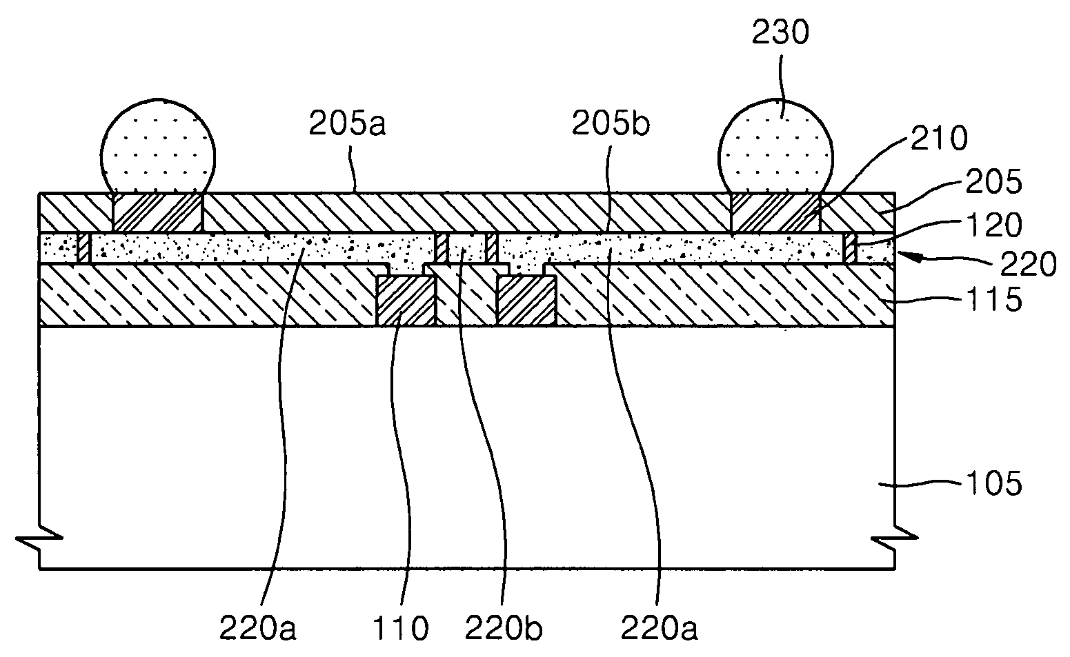
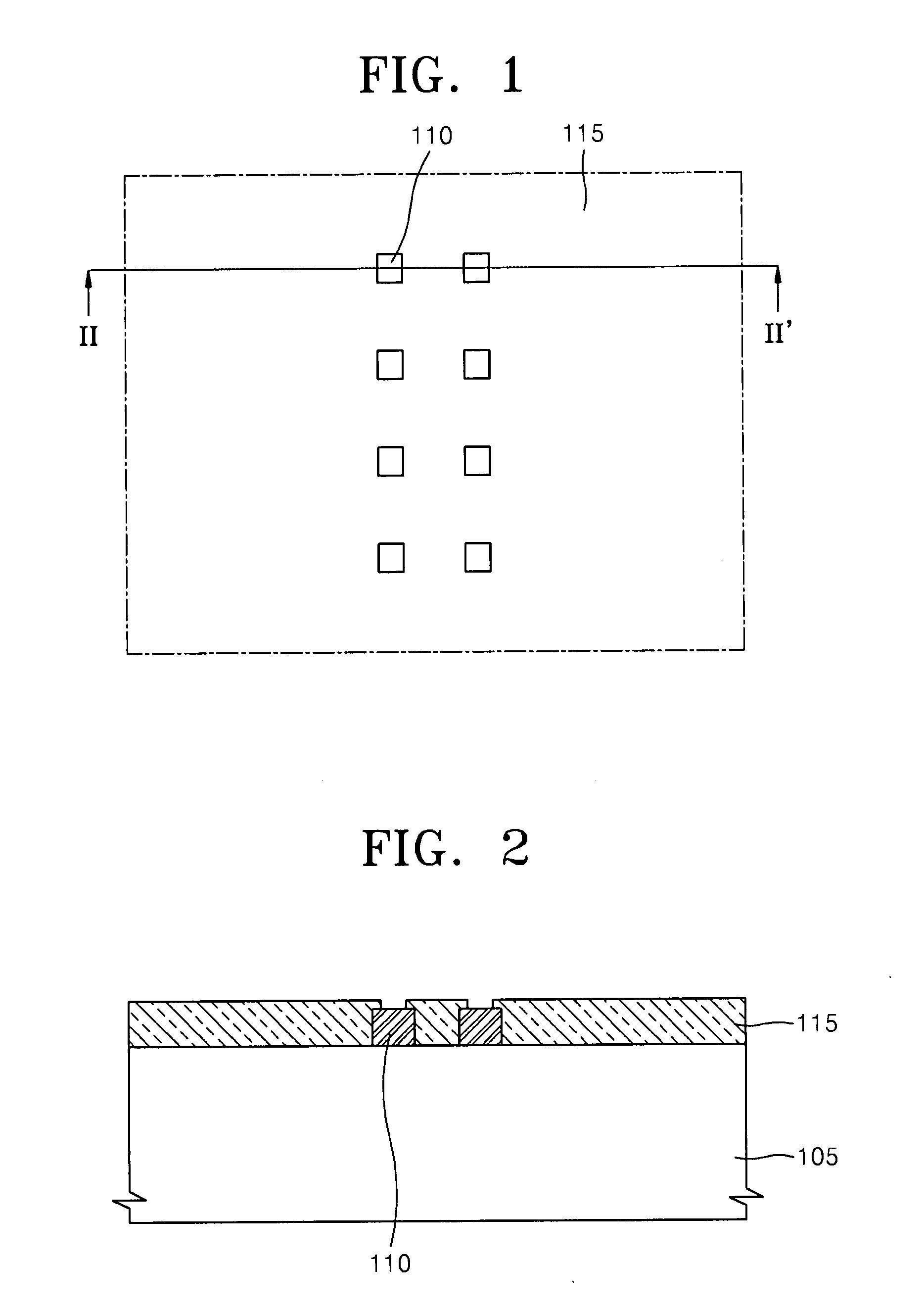
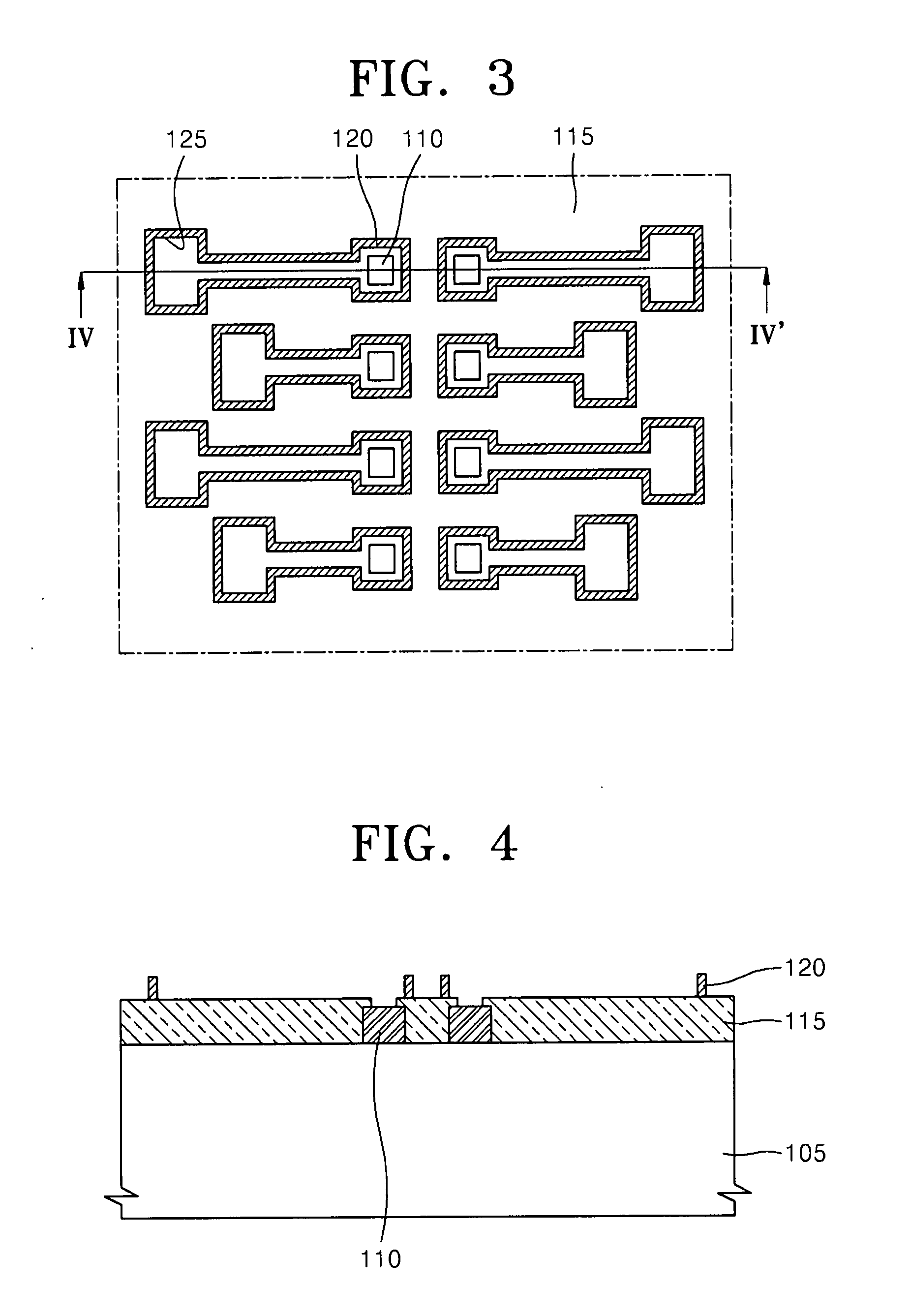
The patent text describes a semiconductor device and a method of fabricating it. The semiconductor device includes a semiconductor substrate with conductive pads, an insulating isolation layer, a package substrate with conductive pads, and a conductive adhesive layer that connects the two substrates. The interconnection lines between the conductive pads are confined by the insulating isolation layer. The method includes forming the insulating isolation layer on the semiconductor substrate, attaching the package substrate to the semiconductor substrate, and exposing the conductive pads on the package substrate. The technical effects of this patent include higher reliability and more economical fabrication of the semiconductor device.

Problems solved by technology

However, a reliability of the wire bonding may be deteriorated as a size of the semiconductor chips decreases.
However, a conventional method of forming redistributed patterns on a semiconductor substrate may increase fabrication costs, and / or may be difficult to employ in assembling and packaging processes.
Because the semiconductor chip may be exposed to the outside, the semiconductor chip may be vulnerable to external impacts.

Method used


Image

  • Semiconductor device having conductive adhesive layer and method of fabricating the same
  • Semiconductor device having conductive adhesive layer and method of fabricating the same
  • Semiconductor device having conductive adhesive layer and method of fabricating the same

Examples


Embodiment Construction

[0028]Example embodiments will now be described more fully hereinafter with reference to the accompanying drawings. Embodiments may, however, be embodied in many different forms and should not be construed as being limited to the example embodiments set forth herein. Rather, these example embodiments are provided so that this disclosure will be thorough and complete, and will fully convey the scope to those skilled in the art. In the drawings, the thicknesses of layers and regions are exaggerated for clarity.

[0029]Example embodiments will now be described more fully hereinafter with reference to the accompanying drawings. Embodiments may, however, be in many different forms and should not be construed as being limited to the example embodiments set forth herein. Rather, these example embodiments are provided so that this disclosure will be thorough and complete, and will fully convey the scope to those skilled in the art. In the drawings, the thicknesses of layers and regions may be...


PUM


Abstract

In a semiconductor device, a semiconductor substrate may include a plurality of first conductive pads. An insulating isolation layer may be on the semiconductor substrate so as to separate the first conductive pads. A package substrate may include a plurality of second conductive pads. A conductive adhesive layer may connect the first conductive pads and the second conductive pads.

Description

PRIORITY STATEMENT[0001]This application claims the benefit of priority to Korean Patent Application No. 10-2006-0057092, filed on Jun. 23, 2006, in the Korean Intellectual Property Office, the entire contents of which are incorporated herein in their entirety by reference.BACKGROUND[0002]1. Field[0003]Example embodiments relate to a semiconductor device and / or a method of fabricating the same, and for example, to an assembled and packaged semiconductor device and / or a method of assembling and packaging the same.[0004]2. Description of Related Art[0005]A plurality of semiconductor devices may be formed simultaneously using a semiconductor substrate, and / or the plurality of semiconductor devices may be assembled and packaged to come out as products. For example, a conventional semiconductor package may use wire bonding. Wires may be bonded to connect semiconductor chips and a package substrate. However, a reliability of the wire bonding may be deteriorated as a size of the semiconduc...

Claims


Application Information

Patent Timeline
Patent Type & Authority Applications(United States)
IPC IPC(8): H01L23/48H01L21/60
CPCH01L21/4853H01L23/3114H01L2924/0665H01L2924/014H01L2924/01033H01L2224/2919H01L23/49816H01L24/28H01L24/31H01L24/83H01L2224/16H01L2224/838H01L2924/01032H01L2924/01047H01L2924/0781H01L2924/19041H01L2924/00H01L24/05H01L2224/02379H01L2224/05001H01L2224/05008H01L2224/05022H01L2224/05024H01L2224/05139H01L2224/0615H01L2924/00014H01L2224/05599
Inventor CHO, YUN-RAE
Owner SAMSUNG ELECTRONICS CO LTD
Learn More