Offshore monopile wind turbine with triangular support structure

a technology of support structure and wind turbine, which is applied in the direction of wind motor assembly, wind energy generation, sustainable manufacturing/processing, etc., can solve the problems of deformation exceeding the allowable limits, and achieve the effects of reducing the concentration of stress risers, reducing the deformation of the support of the turbine, and improving the distribution of soil resistance loads

Active Publication Date: 2020-04-07
SRINIVASAN NAGAN
View PDF25 Cites 10 Cited by
  • Summary
  • Abstract
  • Description
  • Claims
  • Application Information

AI Technical Summary

Benefits of technology

[0017]Another advantage of the invention is that the two additional skirt piles reduces the pile penetration depth requirement and makes clay layers effective in load transfer at the foundation and provides better distribution of soil resistance loads for a long term service life of the wind tower support structure, and the mudmats supported by the horizontal beams at the mudline provide soil resistance to prevent driving the main pile column further into the seabed soil than is required and also ensure that the support structure has a stable settling on the sea floor.
[0018]Another advantage of the invention is that the internal stiffener rings in the collars connecting the sections of the main monopile column reduce the stress risers (stress concentrations) at the main joints due to the brace members connected to the main column.
[0019]Another advantage of the invention is that the triangular support structure transfers bending moment loads into axial loads in the soil media.
[0020]Another advantage of the invention is that it significantly reduces turbine support deformation at the top of the wind turbine support tower.
[0021]Another advantage of the invention is that the unsupported length of the monopile is reduced and the diameter of the monopile column may be about the same or less than half the size of a conventional monopile column.
[0022]Another advantage of the invention is that it allows the structural components to have a smaller diameter and which can be economically fabricated at an onshore location close to the installation site and reduce high transportation costs.

Problems solved by technology

In SLS failure, the deformation will exceed the allowable limits standards.

Method used


Image

  • Offshore monopile wind turbine with triangular support structure
  • Offshore monopile wind turbine with triangular support structure
  • Offshore monopile wind turbine with triangular support structure

Examples


Embodiment Construction

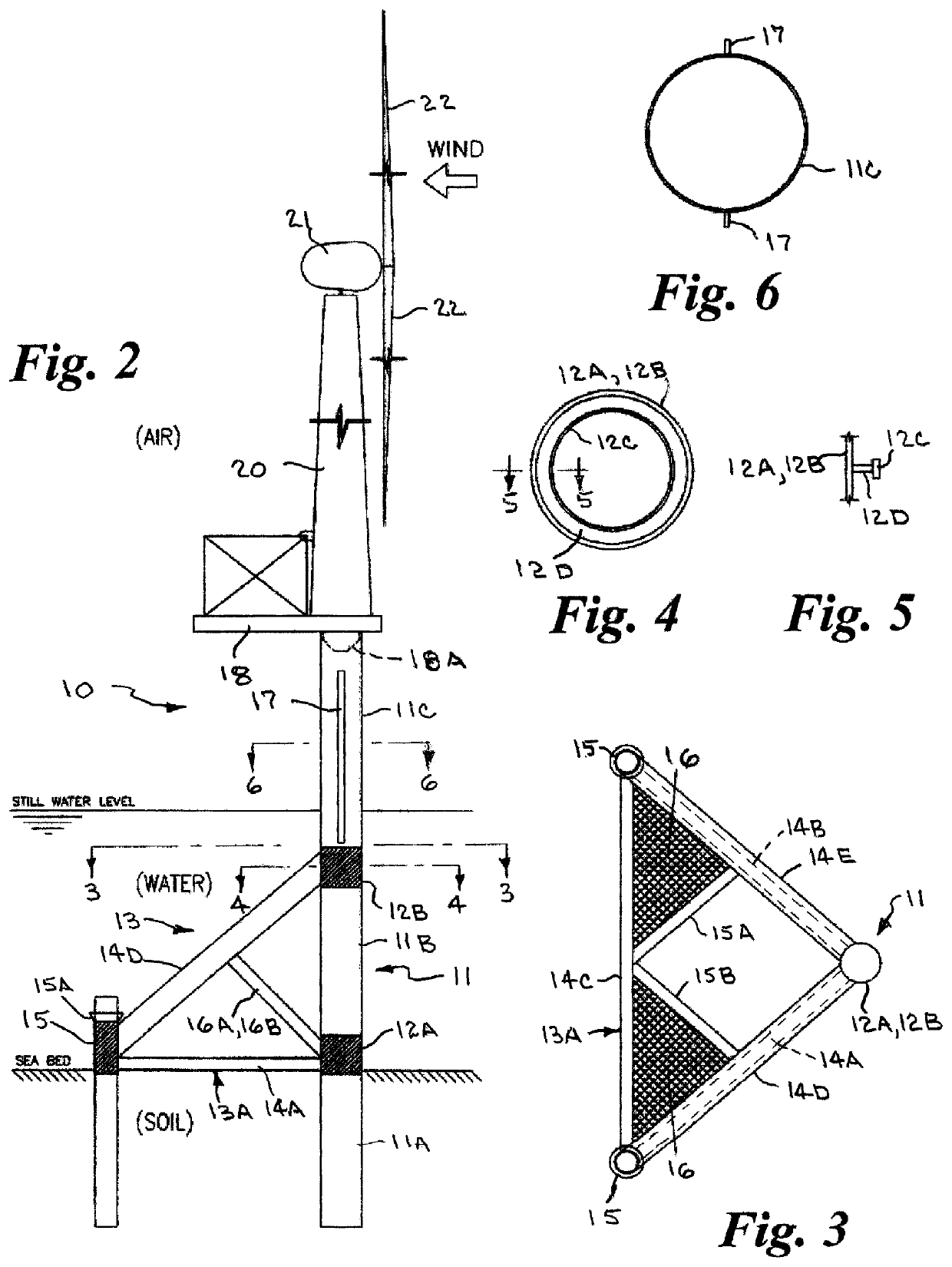
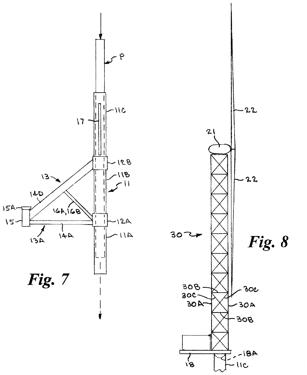
[0034]As used herein, in conjunction with the present invention, the following terms have the following meanings. The term “truss” means a structure that consists of members organized into connected triangles so that the overall assembly behaves as a single object. A truss is made up of a web of triangles joined together to enable the even distribution of weight and the handling of changing tension. The term “tubular” means long, round, and hollow like a tube. The term “knee brace” means a diagonal member placed across the angle between two members that are joined to stiffen and strengthen a framework so constructed.

[0035]Referring to the drawings by numerals of reference, there is shown in FIGS. 2-6, an offshore monopile wind turbine with a triangular support structure in accordance with the present invention, designated generally as 10, secured to a seabed.

[0036]The monopile wind turbine 10 includes an elongate large diameter steel monopile column 11 having a lower section 11A, an...


PUM


Abstract

An offshore monopile wind turbine having an elongate monopile column formed of a lower section, an intermediate section, and an upper section, secured together by connecting collars. A triangular support structure having a triangular three-sided bottom portion extends horizontally outward from one side of the lower connecting collar includes a first pair of lower horizontal tubular beams diverging outwardly with outer ends welded to a respective vertical skirt pile sleeve, a third tubular beam extending between the skirt pile sleeves. An upper pair of tubular beams diverge outwardly and downwardly from the upper connecting collar and are welded to a respective skirt pile sleeve. A horizontal wind turbine platform and elongate wind turbine tower secured to the top end of the elongate upper section of the monopile column includes a nacelle at the top of the turbine tower includes a rotor with three rotor blades.

Description

BACKGROUND OF THE INVENTION1. Field of the Invention[0001]This invention relates generally to offshore wind turbines, and, more particularly to an offshore monopile wind turbine with a triangular support structure having angular beams and braces supported by two skirt piles in addition to the monopile column, horizontal mud mats supported at the mudline, and internal ring stiffeners in the monopile column to reduce stress riser locations where stress is concentrated at the main joints.2. Background Art[0002]Support structures for offshore wind turbines play an important role not only in the engineering performances but also in the total capital cost and the project executing time. Geotechnical soil conditions, the dynamic response of the wind turbine and the installation complexity are involved with the selection of the appropriate support structure.[0003]For shallow water depths, the most commonly used support structures are a monopile and a jacket structure. For water depths up to...

Claims


Application Information

Patent Timeline
Patent Type & Authority Patents(United States)
IPC IPC(8): F03D13/25
CPCF03D13/25F05B2240/95F03D13/10F05B2230/6102Y02E10/72Y02E10/727Y02P70/50
Inventor SRINIVASAN, NAGAN
Owner SRINIVASAN NAGAN
Why Eureka
Try Eureka