Temperature detecting system and method

a technology of temperature detection and detection system, applied in the direction of optical radiation measurement, instruments, sensing radiation from moving bodies, etc., can solve the problems of insufficient motion sensors, insufficient detection of human presence, and certain disadvantages relative to pyroelectric detectors, so as to increase the frequency response of detectors, increase the frequency response, and improve the effect of detection accuracy

Active Publication Date: 2009-03-03
SUREN SYST
View PDF36 Cites 27 Cited by
  • Summary
  • Abstract
  • Description
  • Claims
  • Application Information

AI Technical Summary

Benefits of technology

[0017]The detector in this system can be swept, or directed at one time or another, over all parts of the monitored area. The detector field-of-view movement is created by varying over time the juxtaposition of detector and optical elements directing radiation to the detector from the monitored area. As the sensor scans the monitored area, the detector creates signals due to temperature differences even among static objects and features within the monitored area. In embodiments where the detector is a pyroelectric detector which responds to change in temperature, the scanning of the detector field of view creates a kind of “motion” which allows it to produce information about relative temperatures of static objects in a monitored area. Since humans typically emit more IR radiation than their background, even non-moving humans can be detected with this system.

Problems solved by technology

Since pyroelectric detectors do not respond to static radiation intensity, such sensors have no means to detect the continued presence of a human that has stopped moving.
As noted above, motion sensors are not completely sufficient for detecting human presence.
However, they have certain disadvantages relative to pyroelectric detectors, including relatively high cost.
Thus, they are not used in commercial human presence sensors.

Method used


Image

  • Temperature detecting system and method
  • Temperature detecting system and method
  • Temperature detecting system and method

Examples


Embodiment Construction

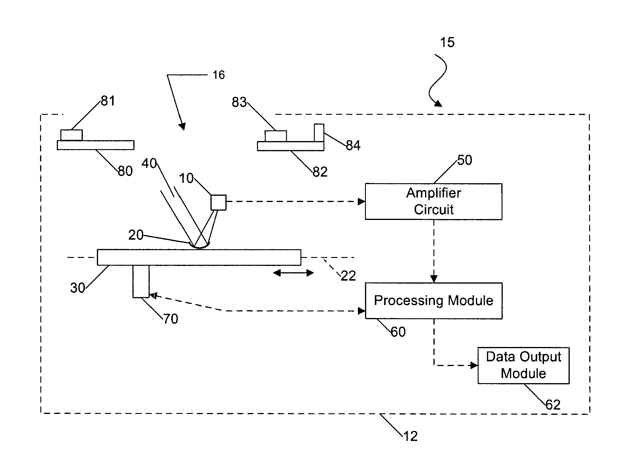
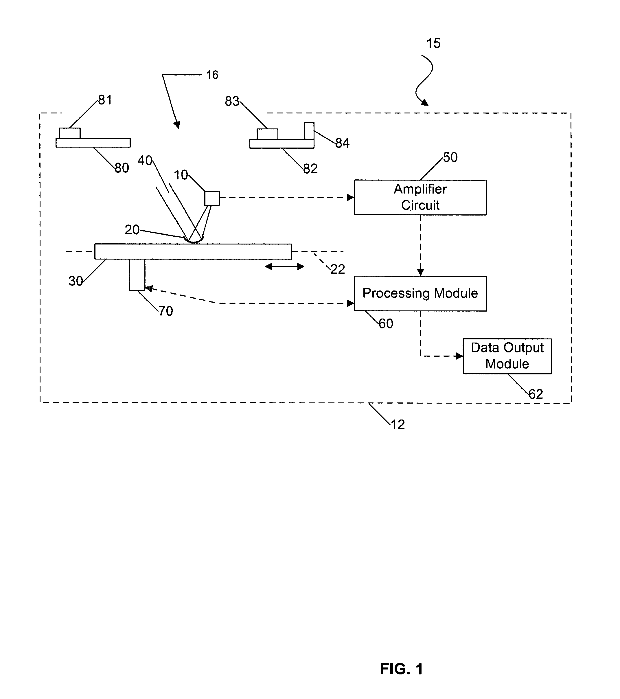
[0029]Certain embodiments as disclosed herein provide for systems and methods for detecting temperature, either for detecting human presence in an area or for general temperature sensing applications, such as signaling a location within a monitored area which has risen to a dangerous temperature. For example, one system and method as disclosed herein allows for use of an infra-red (IR) pyroelectric detector to sense moving or stationary human presence.

[0030]After reading this description it will become apparent to one skilled in the art how to implement the invention in various alternative embodiments and alternative applications. However, although various embodiments of the present invention will be described herein, it is understood that these embodiments are presented by way of example only, and not limitation. As such, this detailed description of various alternative embodiments should not be construed to limit the scope or breadth of the present invention as set forth in the ap...


PUM


Abstract

A temperature detection system for detecting relative or absolute temperatures of objects in a monitored area has at least one infrared (IR) detector and at least one optical element for directing IR radiation within a detector field of view onto the infrared detector. A scanning system is configured to produce relative movement between the optical element and the IR detector such that the detector field of view is scanned across a monitored area to receive IR radiation from objects in the monitored area. A signal processing module for receiving the detector output signal is configured to produce an output profile of the relative temperatures of objects in the monitored area. The IR detector may be a pyroelectric detector.

Description

CROSS-REFERENCE TO RELATED APPLICATION[0001]This application claims the benefit of U.S. Provisional Application No. 60 / 749,737 filed Dec. 12, 2006 under 35 U.S.C. 119(e).BACKGROUND[0002]1. Field of the Invention[0003]The present invention generally relates to a temperature detecting system and method, and is particularly concerned with such a system used for detecting human presence in an area, either for security purposes or for control of lighting and HVAC (Heating, Ventilation and Air Conditioning) so that such features operate only when humans are present.[0004]2. Related Art[0005]In order to reduce energy consumption in homes and other buildings, automatic systems are often used to control lighting and HVAC (“Heating, Ventilation and Air Conditioning”) so that such comfort and convenience features operate only when humans are present. Automatic systems employ sensors to determine human presence. Commonly, several types of motion sensors are used, including Passive Infrared (PIR...

Claims


Application Information

Patent Timeline
Patent Type & Authority Patents(United States)
IPC IPC(8): G01J5/20
CPCG01J1/46G01J5/04G01J5/047G01J5/08G01J5/0806G01J5/0809G01J5/084G01J5/0846G01J5/089G01J5/0893G01J5/34G01J5/522G01J5/0025G01J5/0808G01J5/07G01J5/53
Inventor MICKO, ERIC SCOTT
Owner SUREN SYST
Why Eureka
Try Eureka