Low-harmonics, polyphase converter circuit

a converter circuit and low-harmonic technology, applied in the field of power electronics, can solve the problems of placing a correspondingly severe load on the electrical ac voltage system, and the harmonic effect of the converter circuit is therefore highly undesirable, and achieve the effect of simple and robust design

Active Publication Date: 2009-03-03
ABB (SCHWEIZ) AG
View PDF5 Cites 9 Cited by
  • Summary
  • Abstract
  • Description
  • Claims
  • Application Information

AI Technical Summary

Benefits of technology

[0006]A polyphase converter circuit is disclosed which produces low harmonics with respect to the fundamental of the voltage and the current of an electrical AC voltage system which is connected on the input side to the converter circuit, said converter circuit also being of simple and robust design.

Problems solved by technology

One problem with a polyphase converter circuit in accordance with EP 0913 918 A2 is the fact that, despite the pulse number of 18 for the rectifier units and thus the converter circuit overall, harmonics which are relevant on the primary winding and thus in the electrical AC voltage system and which are greater than the seventeenth harmonic with respect to the fundamental of the voltage and the current of the electrical AC voltage system may occur, and these harmonics then place a correspondingly severe load on the electrical AC voltage system, in particular in the case of a weak electrical AC voltage system having a high rated impedance.
Such effects of harmonics on the converter circuit are therefore highly undesirable.

Method used


Image

  • Low-harmonics, polyphase converter circuit
  • Low-harmonics, polyphase converter circuit
  • Low-harmonics, polyphase converter circuit

Examples


Embodiment Construction

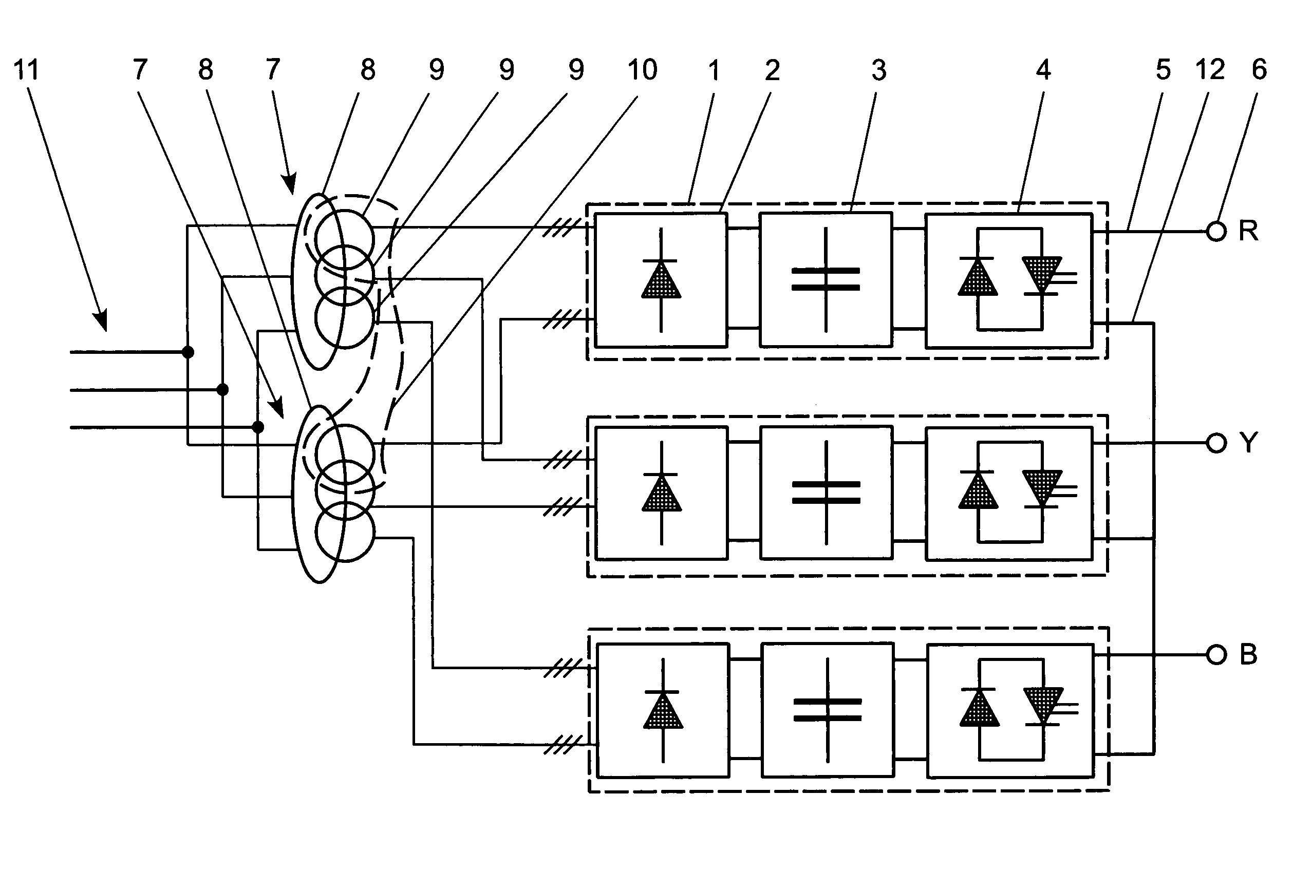
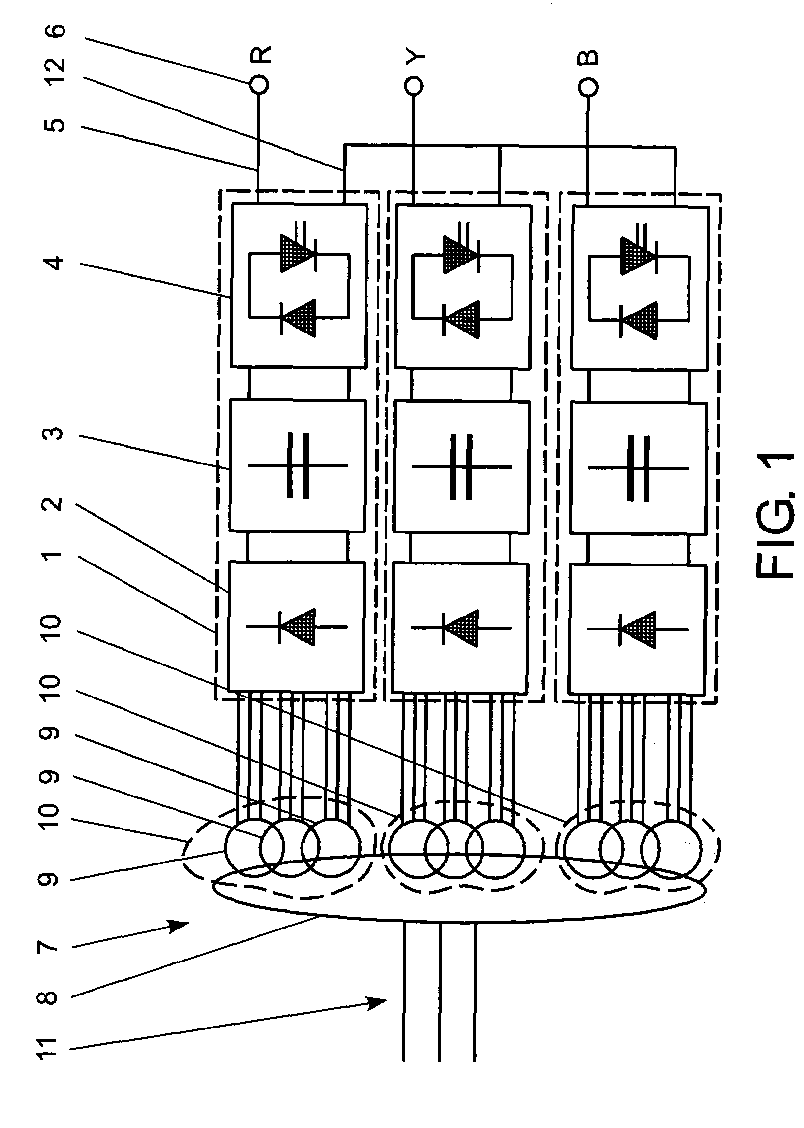
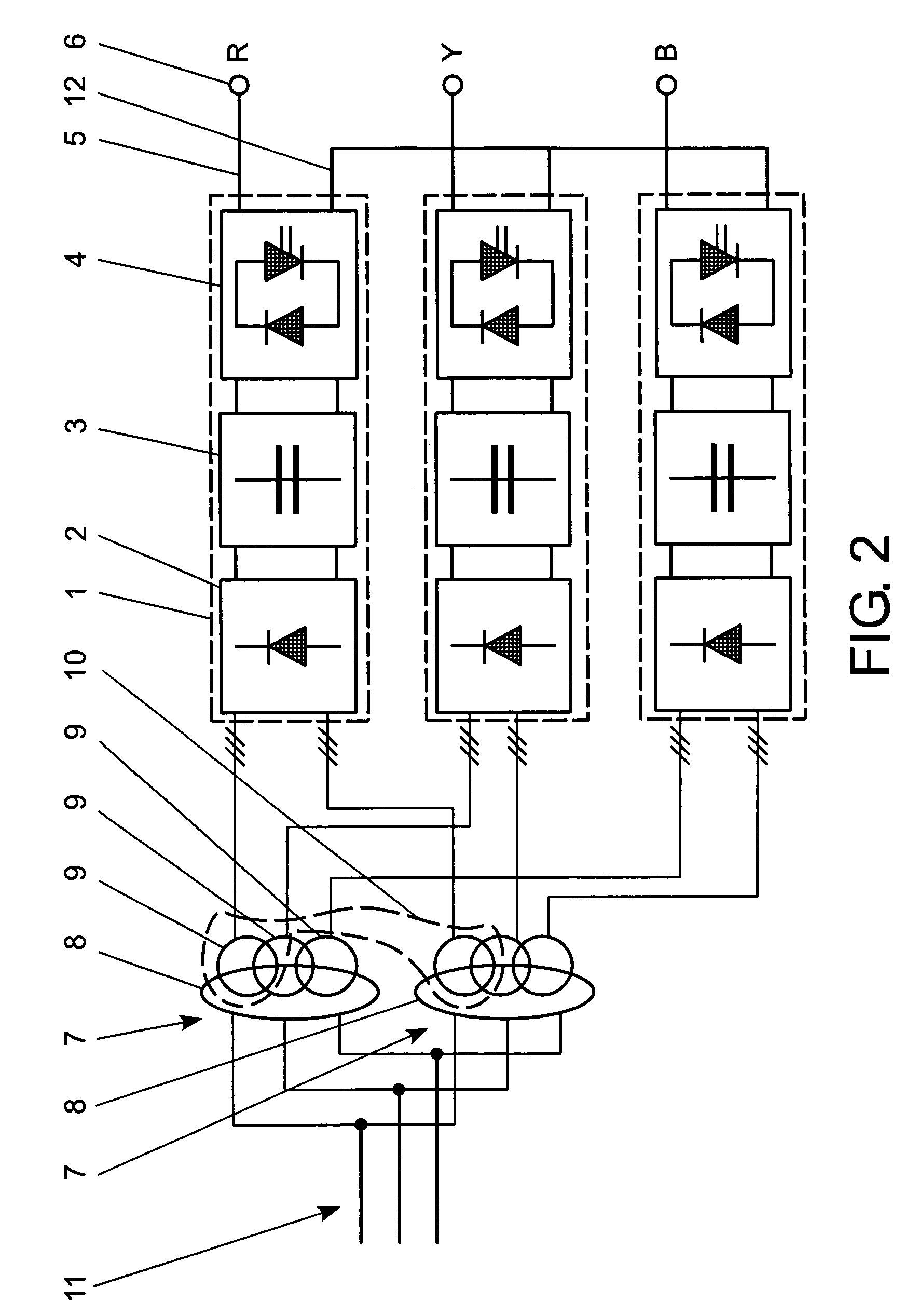
[0023]FIG. 2 shows a first exemplary embodiment of the polyphase converter circuit. The converter circuit shown in FIG. 2 has p=3 phases R, Y, B, p≧3 phases R, Y, B generally being conceivable. As shown in FIG. 2, the converter circuit comprises a converter circuit element 1 provided for each phase R, Y, B, each converter circuit element 1 having a rectifier unit 2, a DC voltage circuit 3 which is connected to the rectifier unit 2 and an inverter unit 4 which is connected to the DC voltage circuit 4. The rectifier unit 2 shown in FIG. 2 has a pulse number of x=12, the pulse number x indicating the number of switching pulses during one period of the voltage of an electrical AC voltage system 11 which is connected on the input side to the converter circuit. Furthermore, a first AC voltage output 5 of each inverter unit 4 forms a phase connection 6. In addition, second AC voltage outputs 12 of the inverter units 5 shown in FIG. 2 are star-connected.

[0024]Accordingly, n transformers 7 c...


PUM


Abstract

A polyphase converter circuit having p≧3 phases (R, Y, B) and a converter circuit element provided for each phase (R, Y, B) is specified, each converter circuit element having a rectifier unit, a DC voltage circuit which is connected to the rectifier unit and an inverter unit which is connected to the DC voltage circuit. In addition, a first AC voltage output of each inverter unit forms a phase connection, and second AC voltage outputs of the inverter units are star-connected. In order to produce harmonics which are as low as possible with respect to the fundamental of the voltage and the current of an electrical AC voltage system which is connected on the input side to the converter circuit, n transformers are provided, each having a primary winding and m three-phase secondary windings, where n≧2 and m≧3. Furthermore, p sets of secondary windings are provided, each set of secondary windings being formed by in each casempthree-phase secondary windings of each transformer, and each set of secondary windings with the associated secondary windings being connected to the rectifier unit of a respective converter circuit element.

Description

CROSS REFERENCE TO RELATED APPLICATIONS[0001]This application claims priority under 35 U.S.C. §119 to EP Application 04405389.0 filed in European Patent Office on 23 Jun. 2004, and as a continuation application under 35 U.S.C. §120 to PCT / CH2005 / 000083 filed as an International Application on 15 Feb. 2005 designating the U.S., the entire contents of which are hereby incorporated by reference in their entireties.FIELD[0002]Polyphase converter circuits relating to the field of power electronics are disclosed.BACKGROUND INFORMATION[0003]Polyphase converter circuits are used today in a wealth of power electronics applications. In this case, the requirements for such a converter circuit are firstly to produce harmonics as little as possible in an electrical AC voltage system which is generally connected on the input side to the converter circuit and also on phases of an electrical load which is more conventionally connected to the converter circuit, and secondly to transmit powers which ...

Claims


Application Information

Patent Timeline
Patent Type & Authority Patents(United States)
IPC IPC(8): H02M5/458H02M7/10
CPCH02M5/458H02M7/49
Inventor STULZ, CHRISTIANEICHLER, CHRISTOPHSUTER, ERICHZUCKERBERGER, ADRIANJORG, PIEDERBERNER, THOMAS
Owner ABB (SCHWEIZ) AG
Why Eureka
Try Eureka