Image pickup apparatus incorporating shake correction

a pickup apparatus and shake correction technology, applied in the field of image pickup apparatus, can solve the problems of preventing accurate shake correction, vibration affecting shake correction, and inability to detect shake angle accurately, so as to achieve the effect of suppressing more reliably the influence of vibration

Inactive Publication Date: 2009-03-03
KONICA MINOLTA PHOTO IMAGING
View PDF12 Cites 15 Cited by
  • Summary
  • Abstract
  • Description
  • Claims
  • Application Information

AI Technical Summary

Benefits of technology

[0010]According to this configuration, the imaging apparatus comprises: the image pickup device for picking up object light; the mirror section for switching an optical path of object light; the retaining member for retaining at least the mirror section; and the shake detection section for detecting a shake of the image pickup device, wherein the shake detection section is provided in the member separate from but indirectly connected to the retaining member via the predetermined connection section. As such, the shake detection section is attached to the separate member (for example, a main body serving as a rigid body composed of an integration of structures other than a unit containing the retaining member retaining the mirror section; specifically, a battery unit in the main body) connected indirectly to the retaining member that retains the mirror section and hence receives directly a vibration at the time of driving of the mirror section (a vibration generated in each driving section in the apparatus is conveniently referred to as a drive vibration, hereafter) with the intervention of the connection section (such as a front chassis, a side chassis, a bottom chassis, and a screw joining these). This avoids that the vibration caused by the driving of the mirror section is directly transmitted to the shake detection section. That is, the vibration is bypassed and damped along a route going through the connection section. This minimizes the influence on the shake detection in the shake detection section. As a result, a clear photographed image is obtained on the basis of the shake correction.
[0020]According to this configuration, the separate member is the battery unit fixed to the retaining member with predetermined spacing via the connection section. Thus, the separation from the retaining member with spacing avoids that the vibration is transmitted to the separate member (battery unit) to which the shake detection section is attached, via a route other than the route going through the connection section (such as via a part in contact with the retaining member, if any). Further, the separate member is a unit serving as a battery accommodating section, and hence generates no vibration. This suppresses more reliably the influence of the vibration on the shake detection in the shake detection section.

Problems solved by technology

As such, when the vibration caused by the driving of the shake correction mechanism, the mirror section, or the like is transmitted to the shake detection section, the vibration affects the shake correction (the shake angle cannot be detected accurately), and prevents accurate shake correction.

Method used


Image

  • Image pickup apparatus incorporating shake correction
  • Image pickup apparatus incorporating shake correction
  • Image pickup apparatus incorporating shake correction

Examples


Embodiment Construction

[0032]Embodiments of the invention are described below with reference to the drawings.

(Description of Camera Appearance Configuration)

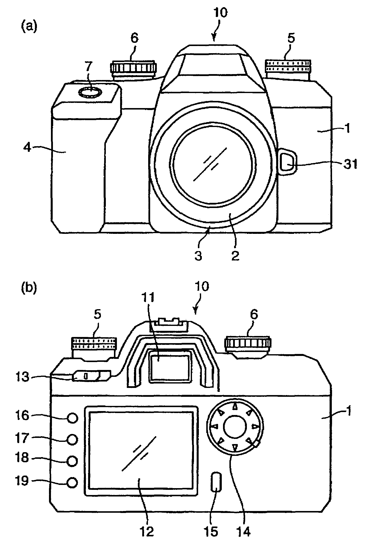
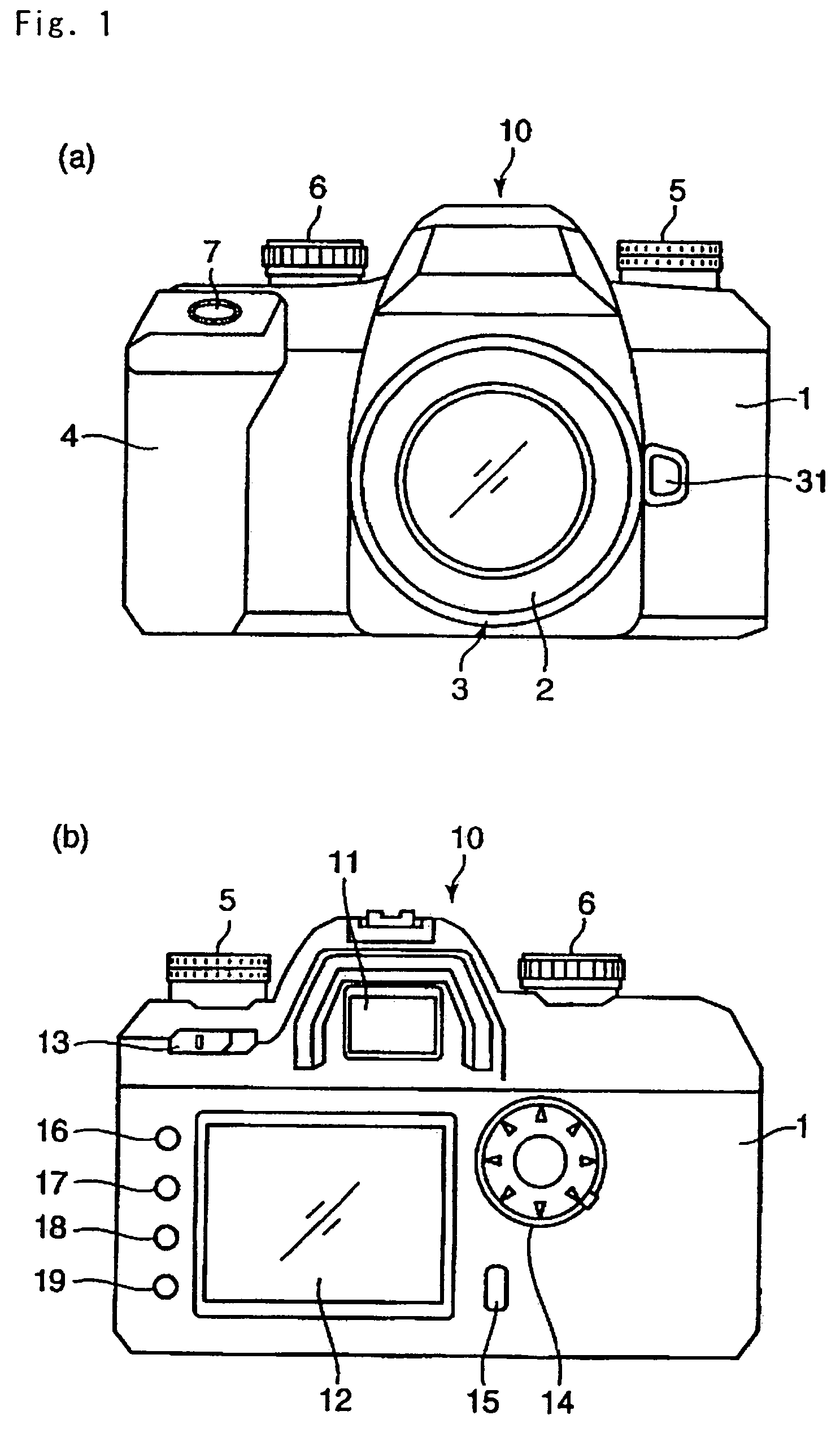
[0033]FIG. 1 is a diagram describing the appearance structure of a digital camera serving as an example of an imaging apparatus according to the invention. FIG. 1(a) is an external front view of the digital camera, while FIG. 1(b) is an external rear view of the digital camera. As shown in FIG. 1(a), the digital camera 10 is a single lens reflex type digital still camera comprising: a camera body 1; and a taking lens 2 (interchangeable lens) attached to an approximate center of the front face of the camera body 1 in an attachable and detachable (interchangeable) manner.

[0034]In FIG. 1(a), the camera body 1 comprises: a mount section 3 which is located in an approximate center of the front face, and to which the taking lens 2 is attached; a grip section 4 protruding in a front left end part and thereby permitting a user to grip (retain) the camera reli...


PUM


Abstract

An imaging apparatus of the invention includes an image pickup device for picking up object light; a mirror section for switching an optical path of the object light; a retaining member for retaining at least the mirror section; and a shake detection section for detecting a shake of the image pickup device. The shake detection section is provided in a member separate from but indirectly connected to the retaining member via a predetermined connection section.

Description

[0001]This application is based on Japanese Patent Application No. 2004-264448 filed in Japan on 10 Sep. 2004, the entire content of which is hereby incorporated by reference.FIELD OF THE INVENTION[0002]The present invention relates to an imaging apparatus such as a digital camera and, in particular, to an imaging apparatus provided with a shake correction mechanism for correcting a camera shake and a shake detecting mechanism for detecting the shake.DESCRIPTION OF RELATED ART[0003]In recent years, in some imaging apparatuses such as digital cameras, a high magnification zoom lens is incorporated that allows a single apparatus to cover a wide range of photographing. Especially in such cameras incorporating a high magnification zoom lens, a “shake” such as a camera shake immediately affects the photographing. Thus, some of such cameras employ a shake correction mechanism in which an image pickup device (image pickup sensor) such as a CCD is displaced (moved) in a direction approximat...

Claims


Application Information

Patent Timeline
Patent Type & Authority Patents(United States)
IPC IPC(8): G03B17/00
CPCG03B17/00
Inventor TANAKA, YOSHIHARUHIROSE, YASUHIROINOUE, YOSHIYUKI
Owner KONICA MINOLTA PHOTO IMAGING
Why Eureka
Try Eureka