Attachment for a surveyor's instrument

a technology for surveyors and instruments, applied in the field of surveyors' instruments, can solve the problems of time-consuming process and laborious task of driving nails or rebar, and achieve the effect of eliminating the connection structur

Inactive Publication Date: 2009-03-10
ENOCH COX & JANICE E COX OR THEIR SUCCESSOR CO TRUSTEES OF THE COX JOINT REVOCABLE TRUST
View PDF8 Cites 59 Cited by
  • Summary
  • Abstract
  • Description
  • Claims
  • Application Information

AI Technical Summary

Benefits of technology

[0011]In any of the above embodiments, the coupling and cap are joined by an associated connecting structure. However, the connecting structure may be eliminated by securing the coupling and cap directly to the can, thus using the can as the connecting structure.

Problems solved by technology

Because it is difficult to make a hole precisely at the correctly determined target point, multiple shootings are generally necessary before the surveyors are satisfied with the accuracy of a hole.
This process is time consuming, not only because it is repetitious, but because it requires the use of separate instruments and tools to shoot, mark and monument points.
Moreover, depending on the nature of the surface to be marked, driving the nails or rebar can be a laborious task.

Method used


Image

  • Attachment for a surveyor's instrument
  • Attachment for a surveyor's instrument
  • Attachment for a surveyor's instrument

Examples


Embodiment Construction

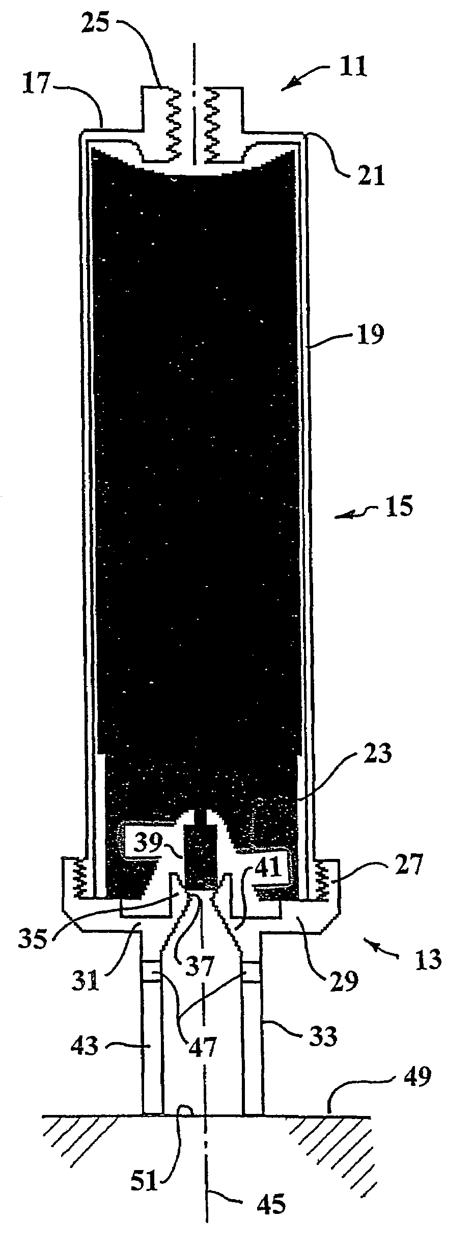
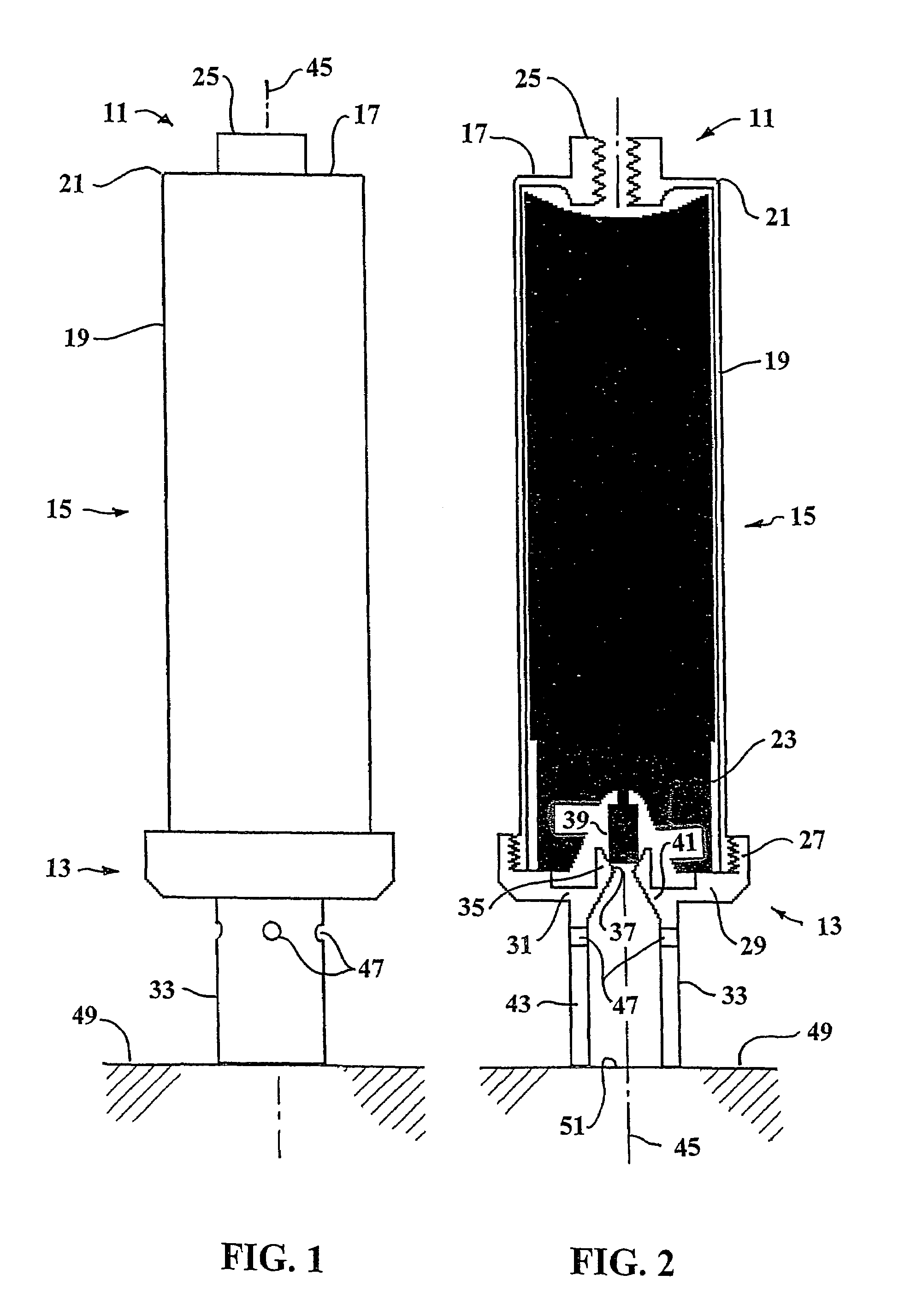
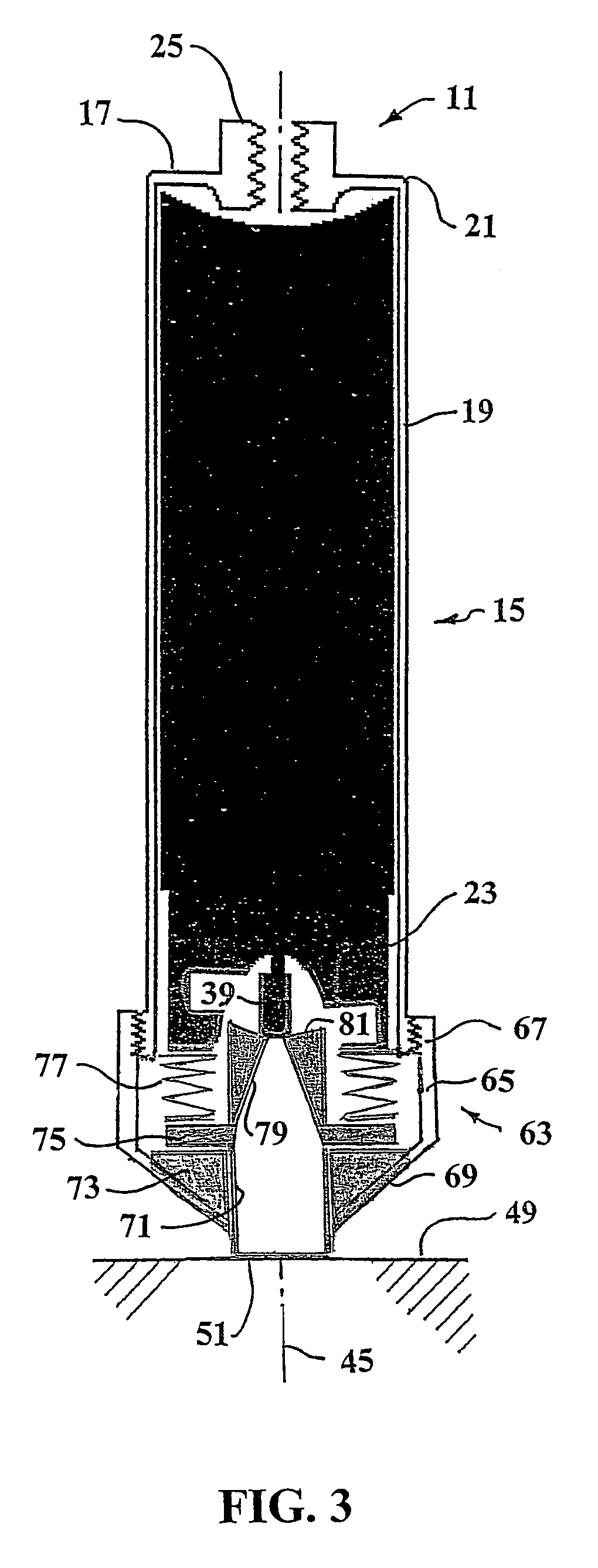
[0017]Looking at the Figures, the target surface marking attachment for a surveyor's instrument has a coupling 11, a cap 13 and a co-operable supporting structure 15 to hold this assembly together for movement in unison. As shown, the coupling 11 and the supporting structure 15 consist of the top 17 and the side walls 19 of a container 21. The container 21 is contoured to hold a can 23 of aerosol paint in an inverted orientation. The height of the container 21 is substantially the same as the height of the can 23. Thus, when the cap 13 covers the open bottom of the container 21, the can 23 cannot slide axially in the container 21.

[0018]The top 17 of the container 21, as shown, has a central internally threaded tube 25 into which the lower end of the surveyor's instrument (not shown) can be threadedly engaged. The cap 13, as shown, is threadedly engaged 27 to the bottom of the container 21 and has a peripheral interior flange 29 against which the rim of the can 23 is sealed. The inte...


PUM


Abstract

An attachment triggers dispensation of paint through the valve of an inverted aerosol can onto a surface target in response to manipulation of a surveyor's rod or pole. A coupling connects the attachment to the lower end of the surveyor's instrument and a cap seals against the valve end of the inverted aerosol can. A support structure holds the coupling, the inverted aerosol can and the cap together for motion in unison. A nozzle defines a path of pneumatic communication from the valve through the cap. The portion of the cap surrounding the nozzle is resiliently pliable so that, when the nozzle is rested on and the surveyor's instrument is pressed toward the surface target, the resiliently pliable portion of the cap flexes to actuate the valve and dispense paint through the nozzle onto the surface target.

Description

BACKGROUND OF THE INVENTION[0001]This invention relates generally to surveying equipment and more particularly concerns a target marking attachment for a surveyor's line rod, prism pole, GPS system rover rod or the like.[0002]In present practice, surveying partners determine a target point by shooting a line and distance using surveyors' instruments and making a hole in the surface at the correct target point. Because it is difficult to make a hole precisely at the correctly determined target point, multiple shootings are generally necessary before the surveyors are satisfied with the accuracy of a hole. Subsequently, the surveyors drive a nail or piece of rebar into the selected hole to monument the point. This process is time consuming, not only because it is repetitious, but because it requires the use of separate instruments and tools to shoot, mark and monument points. Moreover, depending on the nature of the surface to be marked, driving the nails or rebar can be a laborious t...

Claims


Application Information

Patent Timeline
Patent Type & Authority Patents(United States)
IPC IPC(8): B65D83/00
CPCG01C15/02
Inventor COX, ENOCH
Owner ENOCH COX & JANICE E COX OR THEIR SUCCESSOR CO TRUSTEES OF THE COX JOINT REVOCABLE TRUST
Why Eureka
Try Eureka