Method and apparatus for a drip tray screen

Active Publication Date: 2009-09-03
LANCER PARTNERSHIP
View PDF14 Cites 7 Cited by
  • Summary
  • Abstract
  • Description
  • Claims
  • Application Information

AI Technical Summary

Benefits of technology

[0011]In accordance with the present invention, a drip tray trap divides a cavity of the drip tray into an inlet chamber and an outlet chamber. The trap includes perforations to permit the passa

Problems solved by technology

A convenience store operator must be aware of the condition of the drip tray or the drip tray will overflow, thereby causing additional problems.
Further, draining drip trays are susceptible to partial clogging which reduces flow, as well as complete clogging, which may cause a flooding problem.
However, this type of strainer or trap does not account for the build up of unwanted or misdelivered ice in the drip tray.
Further problems with the in-line strainers include the collection o

Method used


Image

  • Method and apparatus for a drip tray screen
  • Method and apparatus for a drip tray screen
  • Method and apparatus for a drip tray screen

Examples


first embodiment

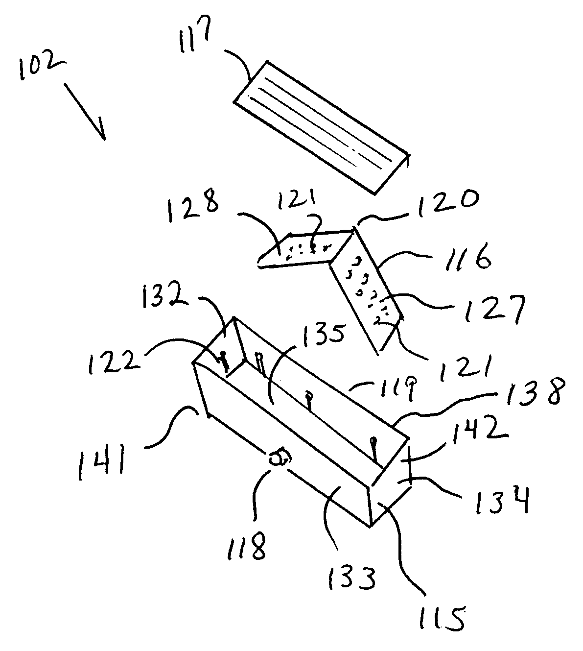
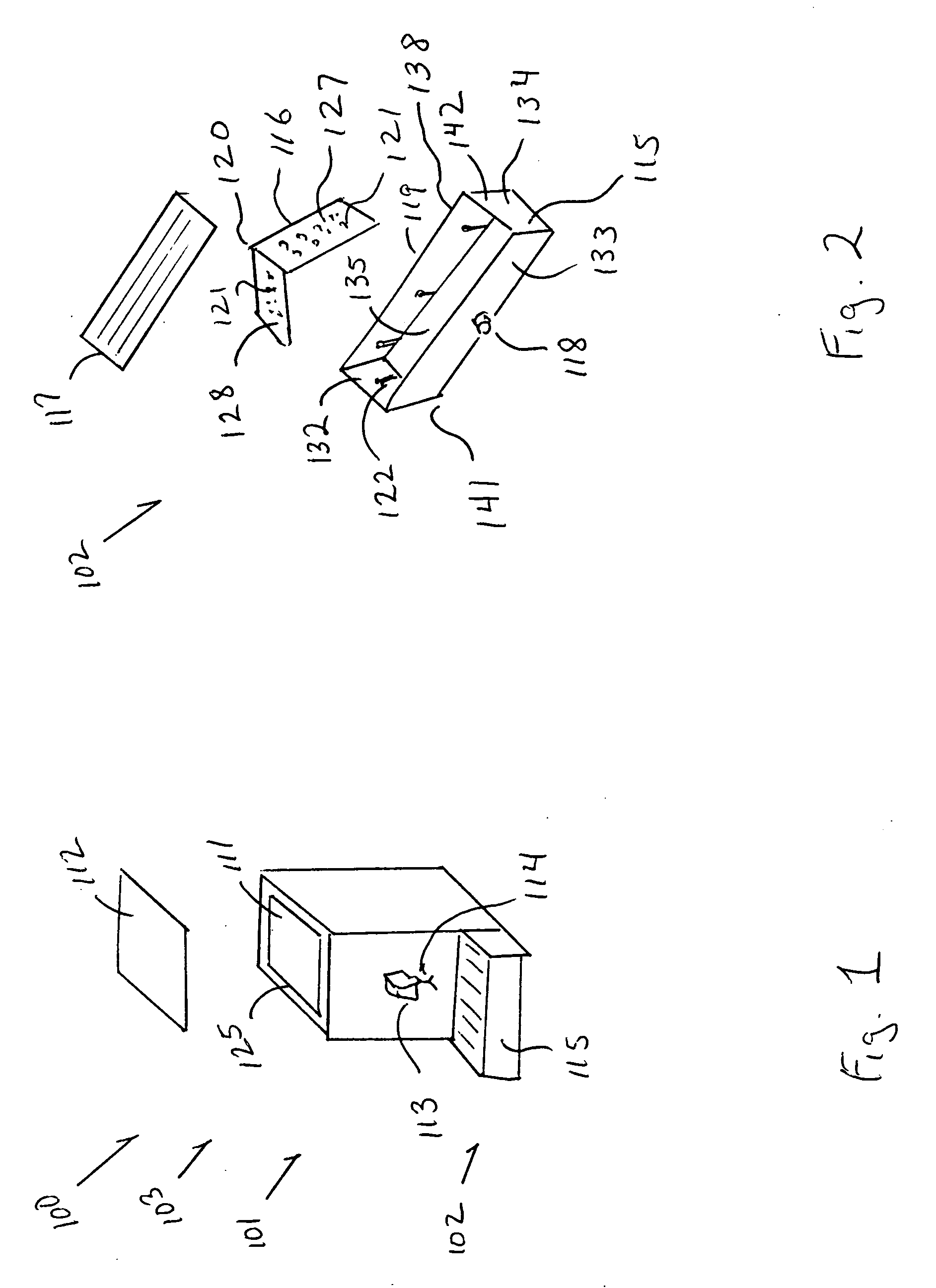
[0047]The drip tray assembly 102 includes a tray 115, a trap 116, and a cup rest 117. The tray 115 includes first through fourth walls 131-134 disposed vertically and a floor panel 135 that form a tray capable of holding fluids as well as solid products. The tray further includes a first end 141 and a second end 142. The floor panel 135 is disposed horizontally and connects to each of the walls 131-134 to create a tray having an interior cavity 119 with an inlet 138. The tray 115 may be formed from virtually any material that is compatible with beverages resists corrosion. Illustratively, in this first embodiment, the tray 115 is formed from acetal butyl styrene. The tray 115 may further include a drain port 118 disposed in a wall 133 nearest the product dispenser 100 or in the floor panel 135. In this particular example, the drain port 118 includes a fitting for attaching to a disposal system (not shown), such as a sewer system or septic system. Accordingly, when the drain port 118...

second embodiment

[0072]FIG. 8e provides a flowchart illustrating the method steps for inserting and removing a drip tray trap 416, according to this Optimally, an operator grasps a handling feature 429 in each hand, as shown in step 25. The operator then moves to step 30, wherein the operator places the trap 416 into the interior cavity 119 of a drip tray 115, such that the handling features 529-530 are disposed upward. In step 35, the operator installs the cup rest 117 above the trap. Upon installation, the trap 416 deflects foreign objects and ice particles, as described in step 40. After use, the operator removes the cup rest 117 to access the trap 416, step 45. Once the cup rest 117 has been removed, the operator removes foreign objects deflected by the trap, step 50. Upon the successful removal of the foreign objects, the operator grasps the handling features 429 and 430, step 55. The operator then lifts the handling features 429 and 430, thereby lifting the trap 416 out of the interior cavity...


PUM


Abstract

A drip tray trap divides a cavity of the drip tray into an inlet chamber and an outlet chamber. The trap includes perforations to permit the passage of liquids, and to restrict the movement of foreign objects and ice cubes to a drip tray outlet, thereby removing the possibility the foreign objects and ice cubes clogging a drip tray drain. The trap includes at least one angled engagement surface and at least one angled engagement surface. The angle of the engagement surfaces forces the ice cubes and foreign objects to move to lowest positions of the inlet chamber. The rerouted ice cubes melt and move through the perforations of the trap, thereby entering the outlet chamber and moving to the drip tray outlet. In a second embodiment, the trap includes handling features to facilitate the insertion and removal of the trap from the cavity of the drip tray for sanitizing.

Description

BACKGROUND OF THE INVENTION[0001]1. Field of the Invention[0002]The present invention relates to product dispensing equipment and, more particularly, but not by way of limitation, to methods and an apparatus for eliminating blockages in a drip tray of a product dispenser.[0003]2. Description of the Related Art[0004]In the area of beverage dispensing, product dispenser manufacturers are forced to provide drip trays in a variety of forms both to meet operator needs, as well as to meet cleanliness requirements. Dependent upon anticipated usage at a consumer location, a product dispenser is outfitted with a draining or a non-draining drip tray. Other factors may include the type of product, the stability of the product, or the availability of an operator to cleanse the drip tray of the product dispenser. However, all drip trays require maintenance to ensure a healthy environment.[0005]Non-draining drip trays, at a minimum, require routine monitoring to ensure that the drip tray has not ...

Claims


Application Information

Patent Timeline
IPC IPC(8): B67D1/16
CPCB67D1/16Y10T137/5762Y10T137/5907
Inventor WELLS, LEROY LEVERTSTUEBS, MICHAEL TROY
Owner LANCER PARTNERSHIP
Why Eureka
Try Eureka