
Ventilated Shoe or Insole

Inactive Publication Date: 2009-02-19
URHO VILJANMAA
View PDF11 Cites 7 Cited by
  • Summary
  • Abstract
  • Description
  • Claims
  • Application Information

AI Technical Summary

Benefits of technology

[0006]One specific objective of the invention is to disclose a ventilated shoe or insole having a very simple ventilation structure which can be implemented with a limited number of elements, easily and at reduced cost, and which also is very versatile being suitable for most divergent shoes and insoles.SUMMARY OF THE INVENTION
[0018]As described above, the invention enables one to achieve a number of benefits compared to the prior-art solutions. The ventilated shoe or insole necessitates no separate pumps or valves. The sufficient ventilation is achieved by means of air channels only requiring a little space, because in the invention, to pump the air, the channels are taken advantage of substantially along their entire length, according to the hose pump principle. The ventilation structure can be implemented in the sole portion of a shoe, in an insole to be fixedly placed into the shoe, or in a separate removable insole. In its simplicity, the ventilation structure of the invention is particularly advantageous to manufacture, making it also applicable to consumer products only allowing few additional costs. The invention is suited to be used in the most divergent shoes, and the material of the air channels, the shape, size and number of the air channels can be chosen to suit an embodiment each time concerned. The invention is very pleasant to the wearer because it does not contain pump cavities being loosely compressed under the foot. Moreover, a ventilation structure that only takes up a little space enables fitting of separate absorption elements into the same shoe or insole with the ventilation structure. The air intake can be implemented at the height of the upper edge of the shoe leg, significantly reducing the possibility of clogging of the air channels. The air channel can also be connected to an external ventilation device that blows air into the channel to effectively dry the shoe.

Problems solved by technology

The stripes joined to another also prevent litter, pebble and other impurities from entering the space between them, which could impede the functioning of the structure.

Method used


Image

  • Ventilated Shoe or Insole
  • Ventilated Shoe or Insole
  • Ventilated Shoe or Insole

Examples


Embodiment Construction

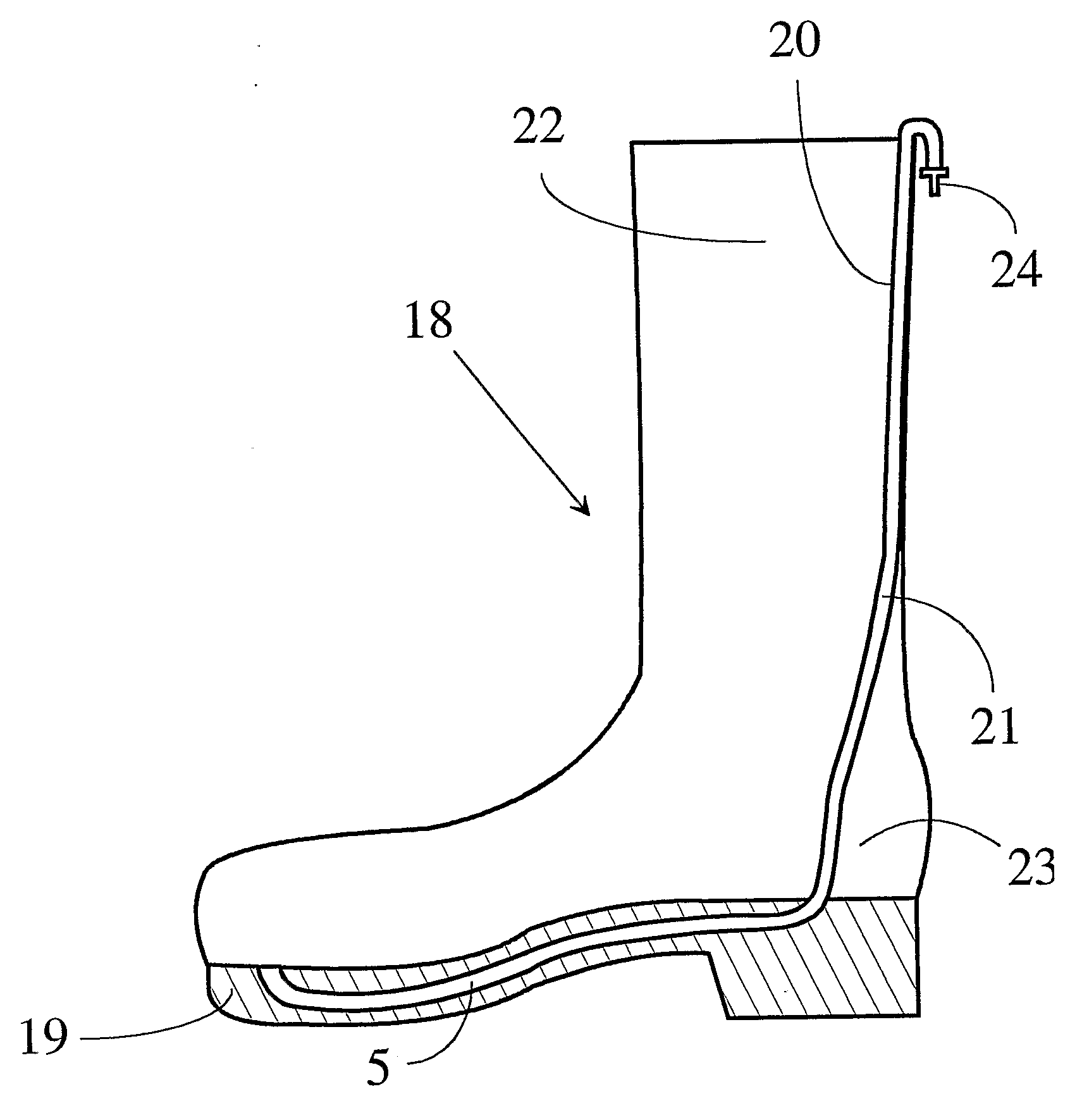
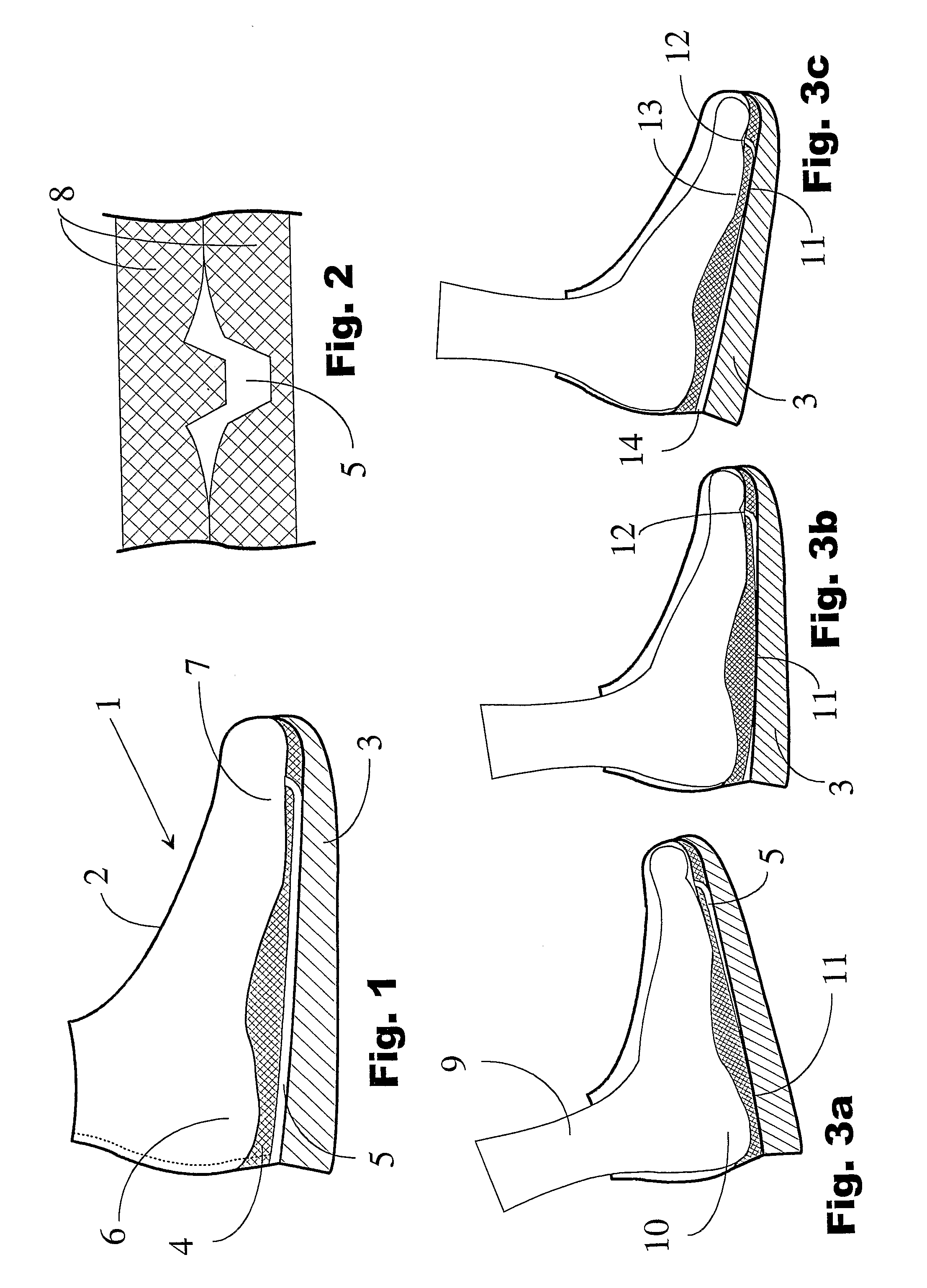
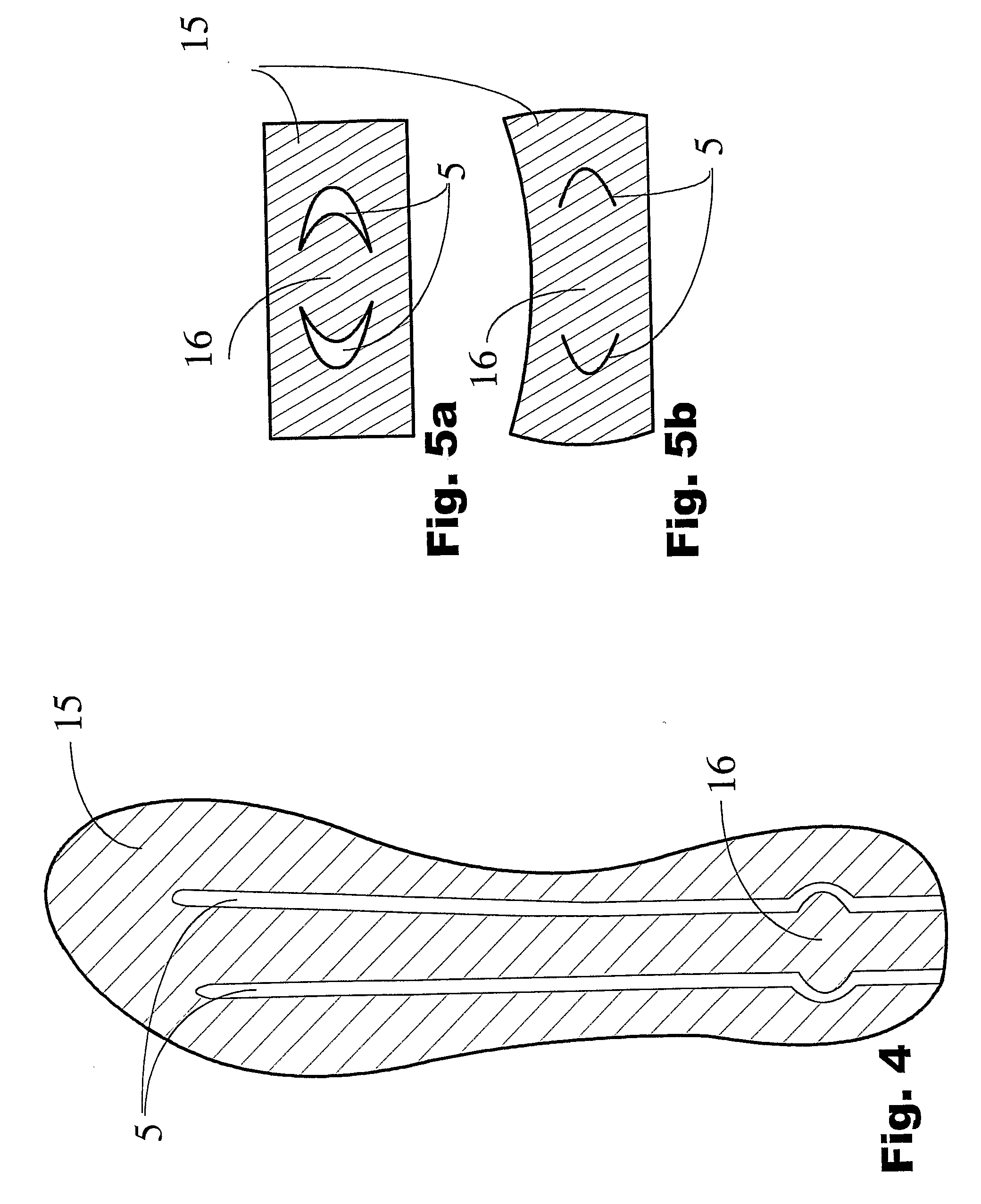
[0027]FIG. 1 is a cross section illustrating a ventilated shoe 1. The shoe includes a top portion 2 of the shoe, a sole portion 3, as well as an insole 4 following the contours of a wearer's foot and made of an elastic material. In the insole there is an elastic air channel 5. The air channel proceeds continuously from the heel portion 6 of the shoe to the toe portion 7. It opens, at the rear end thereof, directly into an air space outside the shoe and at the front part thereof inside the shoe. It would also be possible that the air channel would open into the air space outside the shoe via a continuation channel at the height of the upper edge of the shoe leg, as illustrated by a dash line in the figure. The possible continuation channel can also proceed outside the shoe. The figure illustrates a situation where no weight rests on the shoe 1. In that case, the elastic air channel is open along its entire stretch. The air channel has been so implemented that under weight, it closes ...


PUM


Abstract

A ventilated shoe or insole having a uniform and continuous air channel extending from the heel portion of the sole portion or insole to the toe portion and opening, at the rear end thereof, into the air space outside the shoe or outside the insole, and at the front end thereof, into the inside of the shoe or onto the upper surface of the insole. According to the invention, the air channel is a channel formed by an elastic supporting structure and having a substantially standard cross section that as the stepping motion proceeds, closes tightly phase by phase substantially along the entire stretch thereof under the weight of the foot for transferring air according to the hose pump principle from outside of the shoe or insole into the inside of the shoe or into the upper surface of the insole along the air channel.

Description

FIELD OF THE INVENTION[0001]The present invention relates to a ventilated shoe or insole as defined in the preamble of claim 1.BACKGROUND OF THE INVENTION[0002]Several technical implementations have long been known for ventilating various types of shoes to reduce the temperature in foot and to remove the moisture caused by perspiration. Typical solutions include various combinations of pumping elements and valves preventing backflow of air, where a pumping element is used to transfer fresh air from the rear of the shoe or from outside to the front of the shoe. Due to their complicated structure, these are, however, laborious and expensive to manufacture, and thus are not suited for the mass production of cost-critical consumer products. In particular, valves incur additional expenses and also are susceptible to damage and clogging caused by impurities, after which the ventilation does not work any more. Simpler ventilation structures, that is to say ones to be implemented without ac...

Claims


Application Information

Patent Timeline
IPC IPC(8): A43B7/06A43B13/20A43BA43B7/08A43B17/08
CPCA43B17/08A43B7/08
Inventor HYPPONEN, ALPO
Owner URHO VILJANMAA
Learn More