
Superconducting tube heating device for drying room

A heating device and drying room technology, applied in the field of drying room, can solve problems such as poor ventilation effect, poor dust removal effect, poor drying effect, etc., achieve excellent thermal superconductivity, good heat preservation effect, and improve drying effect of effect

Pending Publication Date: 2021-11-19
盐城韩暖节能科技有限公司
View PDF8 Cites 1 Cited by
  • Summary
  • Abstract
  • Description
  • Claims
  • Application Information

AI Technical Summary

Problems solved by technology

[0003] The purpose of the present invention is to provide a superconducting tube heating device for drying room, to solve the problem that the existing superconducting tube heating device for drying room proposed in the above background technology has poor drying effect, and the existing drying room uses The ventilation effect of the superconducting tube heating device is not good, and the dust removal effect of the existing superconducting tube heating device for the drying room is poor, and the existing superconducting tube heating device for the drying room is low in practicability

Method used


Image

  • Superconducting tube heating device for drying room
  • Superconducting tube heating device for drying room
  • Superconducting tube heating device for drying room

Examples


Embodiment Construction

[0035] The following will clearly and completely describe the technical solutions in the embodiments of the present invention with reference to the accompanying drawings in the embodiments of the present invention. Obviously, the described embodiments are only some, not all, embodiments of the present invention. Based on the embodiments of the present invention, all other embodiments obtained by persons of ordinary skill in the art without making creative efforts belong to the protection scope of the present invention.

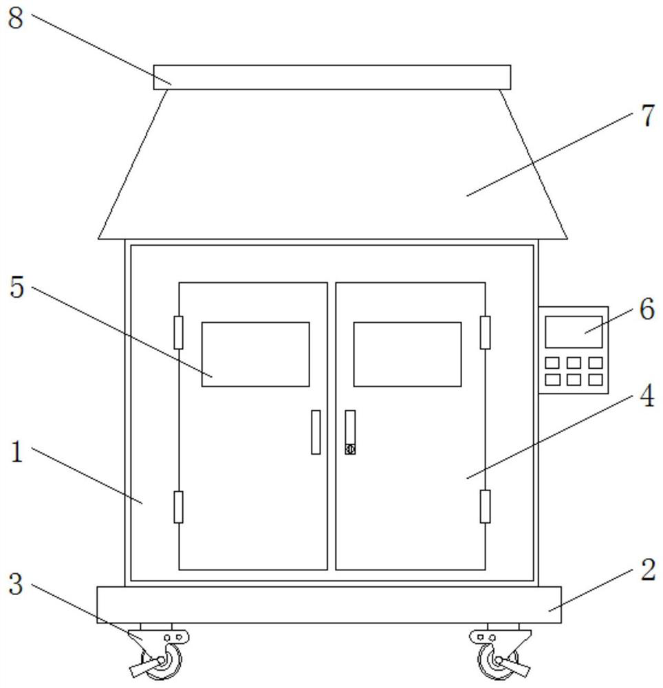
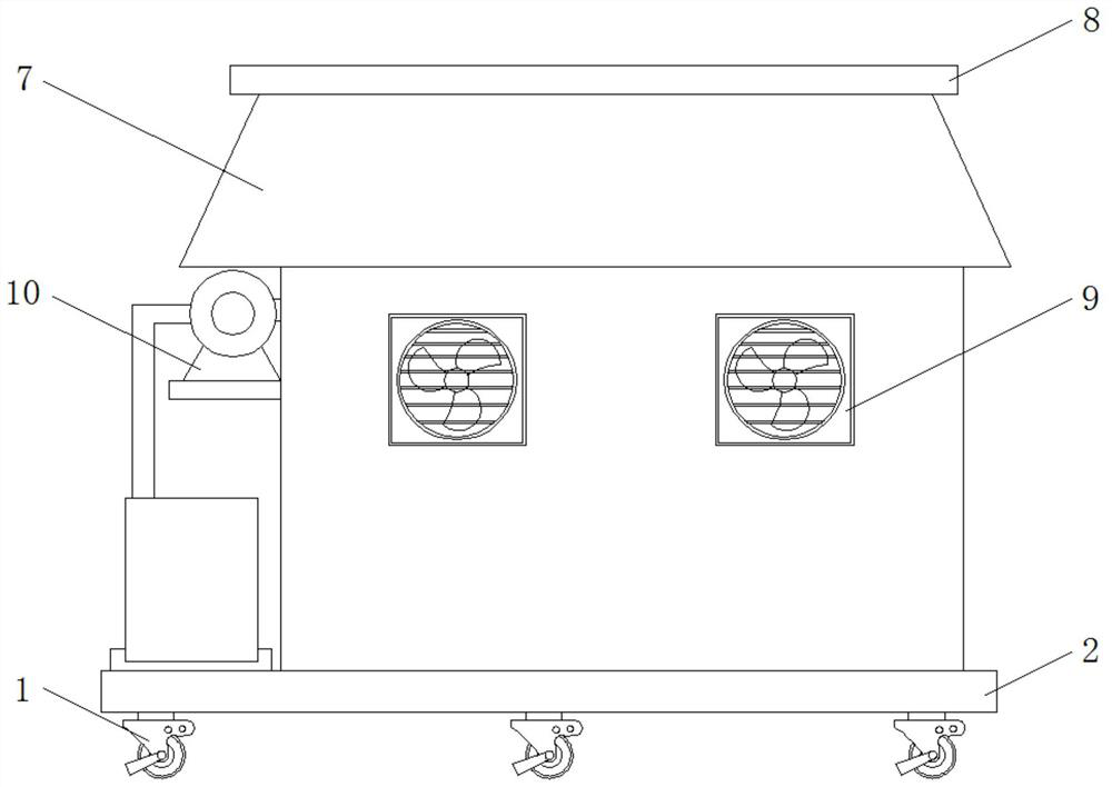
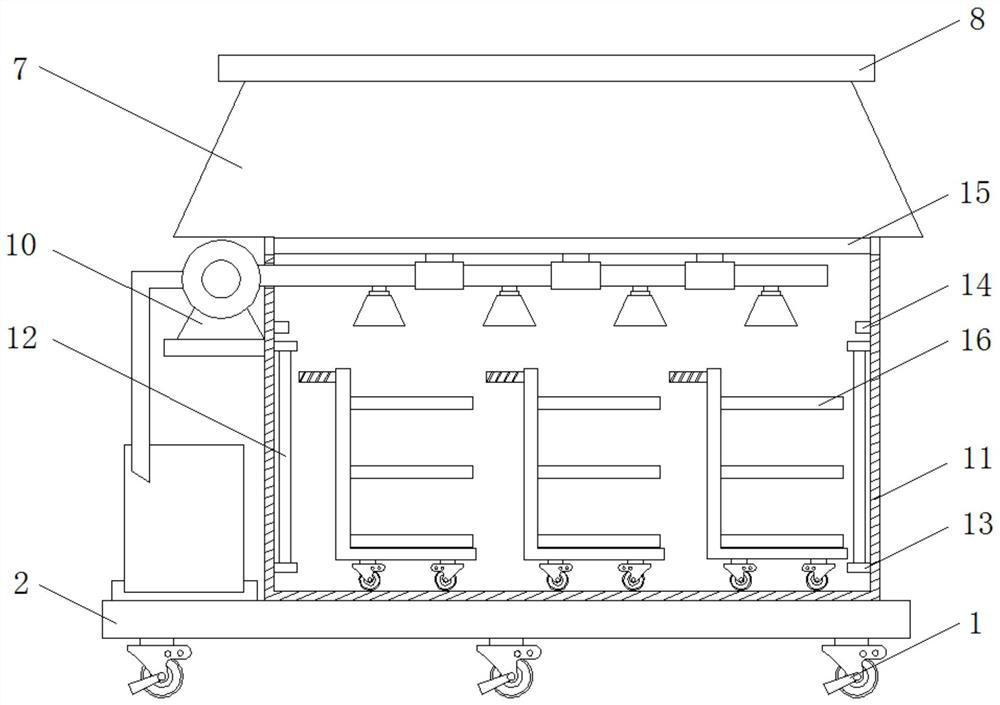
[0036] see Figure 1-7 , the invention provides a superconducting conduit heating device for a drying room, such as figure 1 As shown, the bottom of the main body 1 of the drying room is fixedly installed with a base plate 2, and the bottom of the base plate 2 is equipped with universal wheels 3, six universal wheels 3 are provided, and the universal wheels 3 are symmetrically distributed on both sides of the base plate 2, and the universal wheels 3 are symmet...


PUM


Abstract

The invention discloses a superconducting tube heating device for a drying room. The superconducting tube heating device for the drying room comprises a drying room body, a sealing door, a roof, a ventilation mechanism, a heat preservation layer, temperature sensors and a placement mechanism, wherein a bottom plate is fixedly installed at the bottom end of the drying room body; universal wheels are installed at the bottom of the bottom plate; the sealing door is arranged on one side of the drying room body; a transparent observation window is arranged on the sealing door; the roof is arranged at the top end of the drying room body; the ventilation mechanism is arranged on one side of the drying room body; a dust removal mechanism is arranged on one side of the ventilation mechanism; the heat preservation layer is arranged in the drying room body; superconducting tubes are arranged on the two sides of the interior of the drying room body; the temperature sensors are arranged above the superconducting tubes; a supporting cross rod is arranged above the temperature sensors; and the placement mechanism is arranged in the drying room body. The superconducting tube heating device for the drying room is provided with the dust removal mechanism and the placement mechanism, the dust removal mechanism facilitates dust removal of the interior of the drying room, and the placement mechanism facilitates placement of materials needing to be dried.

Description

technical field [0001] The invention relates to the technical field of drying rooms, in particular to a superconducting conduit heating device for drying rooms. Background technique [0002] The drying room is a kind of drying equipment, which refers to the combination of a series of mechanical equipment that dries the moisture or other liquids on the surface of objects through certain technical means. The popular drying technologies are mainly ultraviolet drying, infrared drying, electromagnetic drying and hot air drying. They have their own characteristics and are widely used in the drying of various mechanical equipment and food. Superconductor, also known as heat pipe, is a special material with rapid temperature uniformity. Its hollow metal tube body makes it light in weight, and its rapid temperature uniformity makes it have excellent thermal superconductivity. , The heat pipe has a wide range of applications. It was first used in the aerospace field, and it has been...

Claims


Application Information

Patent Timeline
Patent Type & Authority Applications(China)
IPC IPC(8): F26B9/02F26B23/04F26B25/00F26B25/06F26B25/08F26B25/12
CPCF26B9/02F26B23/04F26B25/007F26B25/063F26B25/08F26B25/12
Inventor 卞学义陈森林
Owner 盐城韩暖节能科技有限公司
Learn More