
Ventilation system and ventilation method of underwater double-pipe municipal and highway long shield tunnels

A technology of shield tunneling and shield tunneling, which is applied in the field of ventilation systems of underwater double-pipe municipal and highway shield tunnels, and can solve the problems of large shield section, difficulty in implementing shield section engineering, and increased construction cost , Restricting the application of shield tunneling methods and other issues, to achieve the effects of saving construction costs, reducing implementation difficulty and construction risks, and simple ventilation methods

Active Publication Date: 2019-04-19
CHINA RAILWAY LIUYUAN GRP CO LTD
View PDF13 Cites 0 Cited by
  • Summary
  • Abstract
  • Description
  • Claims
  • Application Information

AI Technical Summary

Problems solved by technology

The jet fan is arranged in two sections (arranged along the two ends of the tunnel to the middle), and the civil smoke exhaust duct and the jet fan are installed in the shield section at the same time, resulting in a larger shield section
The increase of the shield section will increase the difficulty of project implementation, construction risk and project cost, which to a certain extent restricts the application of the shield tunneling method in long underwater tunnels

Method used


Image

  • Ventilation system and ventilation method of underwater double-pipe municipal and highway long shield tunnels
  • Ventilation system and ventilation method of underwater double-pipe municipal and highway long shield tunnels
  • Ventilation system and ventilation method of underwater double-pipe municipal and highway long shield tunnels

Examples


Embodiment

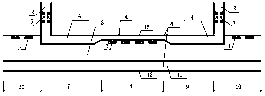
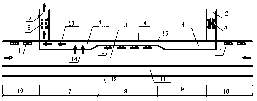
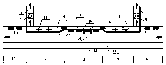
[0026] A ventilation system for an underwater double-pipe municipal and highway long shield tunnel, comprising a shield tunnel 6, the top of the shield tunnel 6 is provided with a civil smoke exhaust duct 4, and both ends of the shield tunnel 6 are provided with The smoke exhaust air shaft 2 connected with the civil smoke exhaust duct 4, the smoke exhaust air shaft 2 is equipped with a smoke exhaust fan and a damper 5; the middle part of the shield tunnel 6 is divided into the shield A section 7 and the shield B section in sequence along the longitudinal direction of the tunnel 8. The area of ​​civil smoke exhaust air duct 4 of shield tunneling section C 9, shield tunnel A section 7, and shield tunnel C section 9 is equal, and the area of ​​civil smoke exhaust duct 4 of shield tunnel B section 8 is equal to that of shield tunnel A section 7 2 / 5-3 / 5 of the area of ​​the smoke exhaust duct 4, the shield B section 8 and the open-cut and buried section 10 at both ends of the shield...


PUM


Abstract

The invention belongs to the technical field of municipal and road shield tunnels, and particularly relates to a ventilation system and ventilation method for an underwater double-pipe municipal and road long and large shield tunnel. The ventilation system is characterized in that a civil engineering smoke exhaust air duct is arranged on the top of the shield tunnel; smoke exhaust air shafts connected with the civil engineering smoke exhaust air ducts are arranged at the two ends of the shield tunnel correspondingly; smoke exhaust fans and air valves are arranged in the smoke exhaust air shafts; the middle portion of the shield tunnel is sequentially divided into a shield section A, a shield section B and a shield section C in the longitudinal direction of the tunnel; the areas of the portions, on the shield section A and the shield section C, of the civil engineering smoke exhaust air duct are equal; the area of the portion, on the shield section B, of the civil engineering smoke exhaust air duct accounts for 2 / 5 to 3 / 5 of the area, on the shield section A, of the civil engineering smoke exhaust air duct; and jet fans are arranged on the shield section B and open-cut and concealed sections at the two ends of the shield tunnel correspondingly. By means of the ventilation system and the ventilation method, the size requirement of the ventilation scheme for the long and large shield fracture surface is reduced, the project implementation difficulty and the construction risk are lowered, and the engineering construction cost is saved.

Description

technical field [0001] The invention belongs to the technical field of municipal and highway tunnels, and in particular relates to a ventilation system and a ventilation method for underwater double-pipe municipal and highway long shield tunnels. Background technique [0002] The selection of the ventilation mode of an underwater tunnel is related to various factors such as the length of the tunnel, traffic flow, driving mode, environmental protection requirements at the entrance of the tunnel, and tunnel construction methods. At present, the commonly used tunnel ventilation methods include full horizontal, semi horizontal, longitudinal ventilation and longitudinal ventilation + focused smoke exhaust. [0003] The full horizontal and semi-horizontal ventilation methods need to set up special air ducts and fan rooms. The investment in civil engineering is large, and the later ventilation operation costs are high. In the event of a fire, the stratification of smoke can be effe...

Claims


Application Information

Patent Timeline
Patent Type & Authority Patents(China)
IPC IPC(8): E21F1/00
CPCE21F1/003
Inventor 梁艳唐上明范国刚谢朝军朱世友贺维国徐韬姜宝臣丁远见褚凯何潇剑张瑞魏雪胡建国曾亮王东伟曹楷李金龙魏志华杨孝军赖永进廖荣徐美智余露茜
Owner CHINA RAILWAY LIUYUAN GRP CO LTD
Learn More