
Ink jet printing apparatus and ink jet printing method

a printing apparatus and ink jet technology, applied in the field of ink jet printing apparatus and ink jet printing method, to achieve the effect of improving the print quality

Inactive Publication Date: 2009-03-10
CANON KK
View PDF23 Cites 15 Cited by
  • Summary
  • Abstract
  • Description
  • Claims
  • Application Information

AI Technical Summary

Benefits of technology

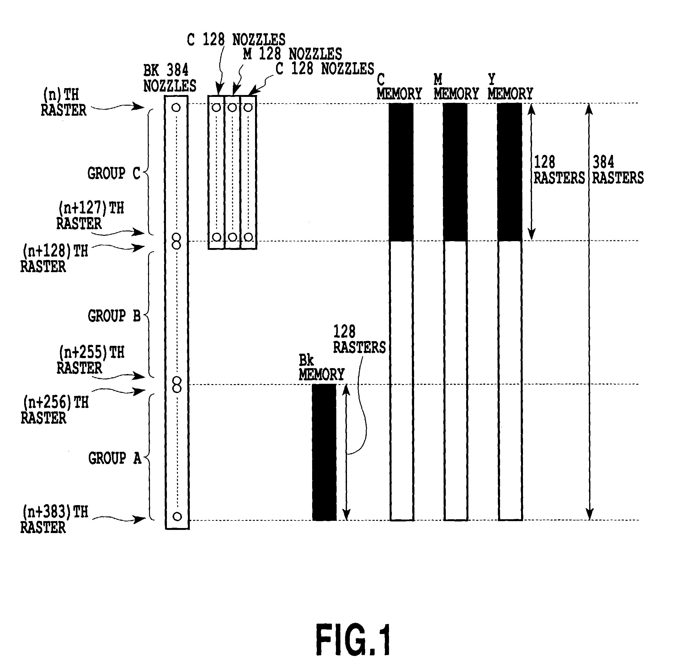
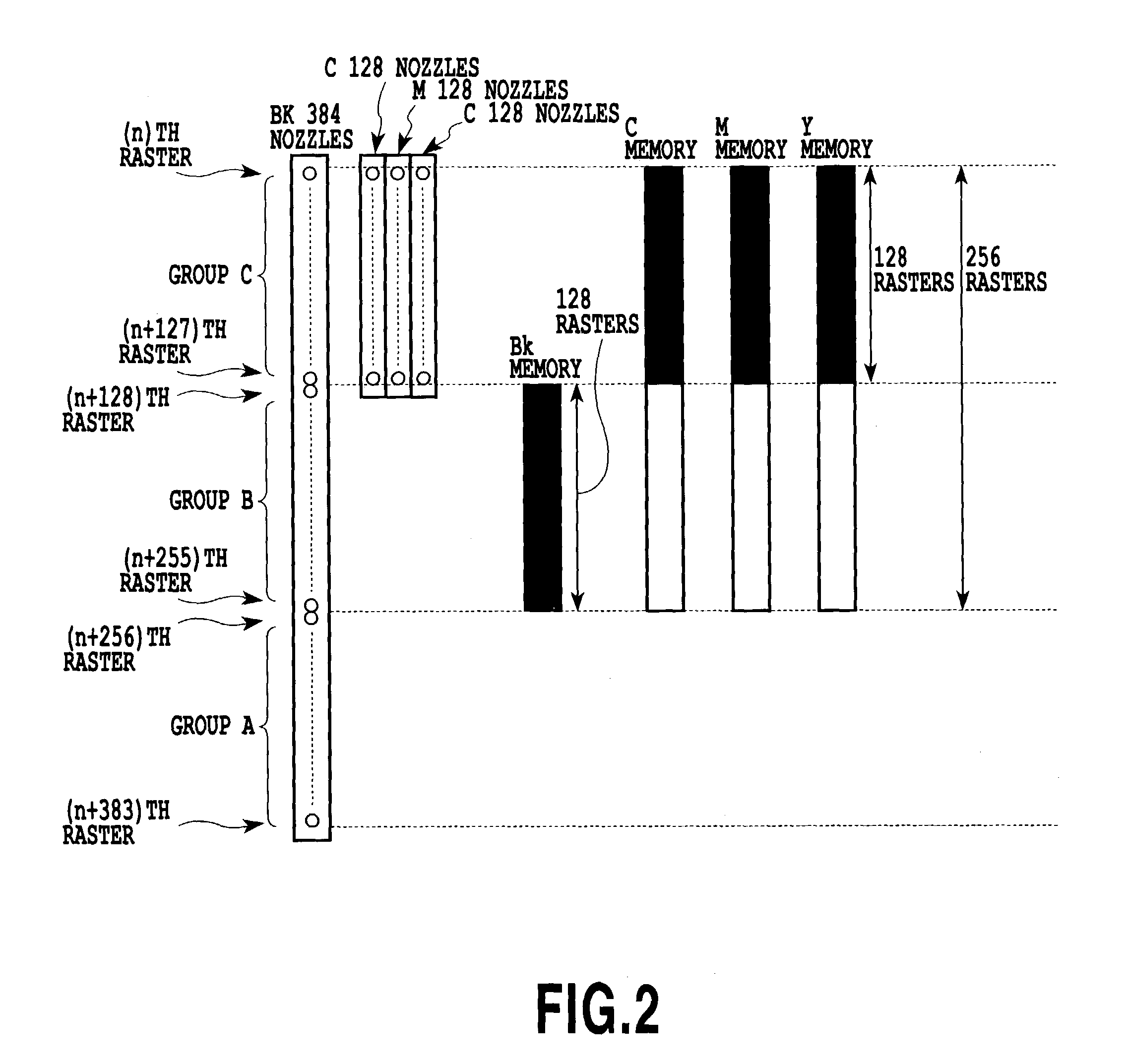
The present invention provides an ink jet printing apparatus and method that can handle both the normal print data transfer mode and the offset transfer mode by changing the positions of nozzles used in the print heads. This allows the printing apparatus to use optimum nozzles for each mode, resulting in improved print quality and reduced memory usage. Additionally, the invention uses a longitudinal array print head configuration and automatically sets the active nozzle positions according to the offset of the print data transferred from the host computer, ensuring reliable printing. Overall, the invention improves the flexibility and efficiency of ink jet printing.

Problems solved by technology

In this case, the print data source, such as a host computer, does not perform the offset processing in which the print data is offset before being supplied to the printing apparatus.

Method used


Image

  • Ink jet printing apparatus and ink jet printing method
  • Ink jet printing apparatus and ink jet printing method
  • Ink jet printing apparatus and ink jet printing method

Examples


first embodiment

[0085]This embodiment of the invention concerns an ink jet printing in which ink is ejected from nozzles of a plurality of print heads onto a print medium to form an image and in which active nozzles are selected according to a transfer mode in which print data is transferred from the host computer to the printing apparatus (print data transfer scheme).

[0086](Configuration of Printing Apparatus)

[0087]FIG. 5 is a perspective view schematically showing a construction of essential portions of an example ink jet printing apparatus applying the present invention. In FIG. 5 a plurality (four) of head cartridges 1A, 1B, 1C, 1D are removably mounted on a carriage 2. The cartridges 1A-1D are each provided with a connector for receiving a signal to drive the print head. In the following description, an expression of “printing means (print head or head cartridge) 1” is used to denote the whole printing means 1A-1D or any one of them.

[0088]The plurality of cartridges 1 use different color inks ...

second embodiment

[0104]Next, a second embodiment of this invention will be described.

[0105]In the second embodiment, as shown in FIG. 9, the active nozzle positions are selected for the one-pass bidirectional printing and for the multipass printing, independently of each other.

[0106]In FIG. 9, data to be printed is read at Step-1. Next, Step-2 retrieves information on the print data transfer mode from the header information attached to the print data. Then, Step-3 discriminates whether the printing mode specified is the one-pass mode or multipass mode. If it is discriminated that the one-pass printing mode is specified, Step-4 discriminates the print data transfer mode. If it is discriminated that the normal print data transfer mode is specified, Step-5 performs the active nozzle position setting for the normal print data transfer mode. If the offset transfer mode is found specified, Step-6 performs the active nozzle position setting for the offset transfer mode.

[0107]If Step-3 finds that the multip...


PUM


Abstract

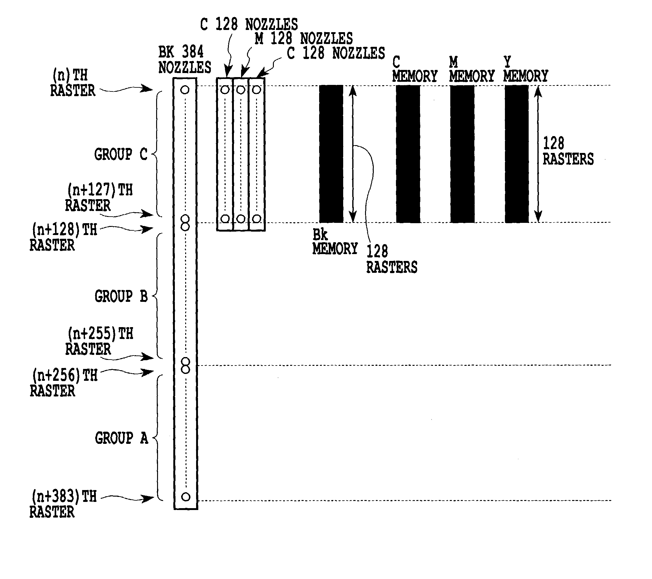
This invention provides an ink jet printing method which ejects different kinds of ink from print heads onto a print medium to form an image according to print data transferred from a predetermined print data source and which can deal with both a normal print data transfer mode and an offset transfer mode. This printing method discriminates the data transfer mode of the print data transferred from the predetermined print data source and sets, in each of the print heads independently, positions of those of the plurality of nozzles that are to be used for printing. Then, the printing method controls the positions of the nozzles to be used according to the data transfer mode discriminated.

Description

[0001]This application claims priority from Japanese Patent Application No. 2002-027474 filed Feb. 4, 2002, which is incorporated hereinto by reference.BACKGROUND OF THE INVENTION[0002]1. Field of the Invention[0003]The present invention relates to an ink jet printing apparatus and an ink jet printing method capable of forming color images by ejecting different kinds of ink from print heads according to print data transferred from a print data source.[0004]The present invention is applicable to any apparatus that uses print mediums such as paper, cloth, leather, nonwoven cloth, OHP sheets and even metals. Examples of applicable apparatus include office automation equipment, such as printers, copying machines and facsimile machines, and industrial manufacturing equipment.[0005]2. Description of the Related Art[0006]Today, with office automation equipment such as personal computers and word processors in widespread use, a variety of printing apparatus and printing methods have been de...

Claims


Application Information

Patent Timeline
Patent Type & Authority Patents(United States)
IPC IPC(8): B41J29/38B41J2/15B41J2/21B41J2/045B41J2/01G06K15/10
CPCB41J2/04528B41J2/04551B41J2/0458G06K15/105G06K15/1814G06K15/1822G06K2215/0094
Inventor TAKAHASHI, KIICHIRO
Owner CANON KK
Learn More