
Duty cycle correction circuit and duty cycle correction method

a duty cycle and circuit technology, applied in the direction of instruments, pulse techniques, generating/distributing signals, etc., can solve the problems of duty cycle correction error, damage to information on duty errors, etc., and achieve the effect of reducing settling time and high accuracy

Active Publication Date: 2009-03-10
SAMSUNG ELECTRONICS CO LTD
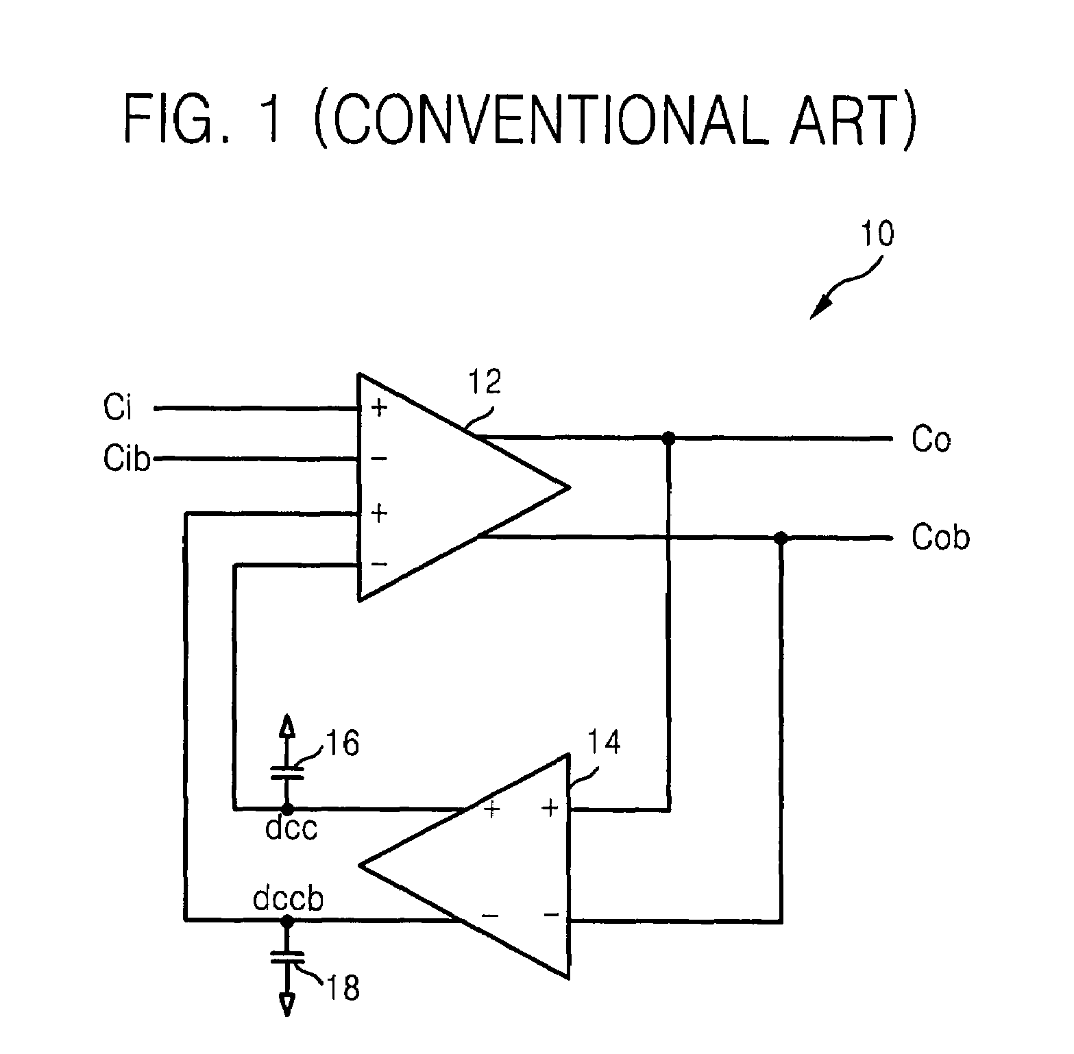
View PDF14 Cites 33 Cited by
  • Summary
  • Abstract
  • Description
  • Claims
  • Application Information

AI Technical Summary

Benefits of technology

[0010]It is therefore a feature of an embodiment of the present invention to provide a duty cycle correction circuit and method thereof having high accuracy.
[0011]It is therefore another feature of an embodiment of the present invention to provide a duty cycle correction circuit and method thereof having a reduced settling time.

Problems solved by technology

Since the analog duty cycle correction circuit stores information on duty error, e.g., deviation from a desired duty cycle, in a capacitor, information on the duty error may be damaged by a leakage current of the capacitor when the analog duty cycle correction circuit is powered off in a power down mode to reduce power consumption.
Current gain may be increased to lessen settling time, but this increase may provoke an error for duty cycle correction after settling time.

Method used


Image

  • Duty cycle correction circuit and duty cycle correction method
  • Duty cycle correction circuit and duty cycle correction method
  • Duty cycle correction circuit and duty cycle correction method

Examples


Embodiment Construction

[0033]Korean Patent Application No. 10-2006-0069573, filed on Jul. 25, 2006, in the Korean Intellectual Property Office, and entitled: “Duty Cycle Correction Circuit and Duty Cycle Correction Method,” is incorporated by reference in its entirety.

[0034]The present invention will now be described more fully hereinafter with reference to the accompanying drawings, in which exemplary embodiments of the invention are illustrated. The invention may, however, be embodied in different forms and should not be construed as limited to the embodiments set forth herein. Rather, these embodiments are provided so that this disclosure will be thorough and complete, and will fully convey the scope of the invention to those skilled in the art. Like reference numerals refer to like elements throughout.

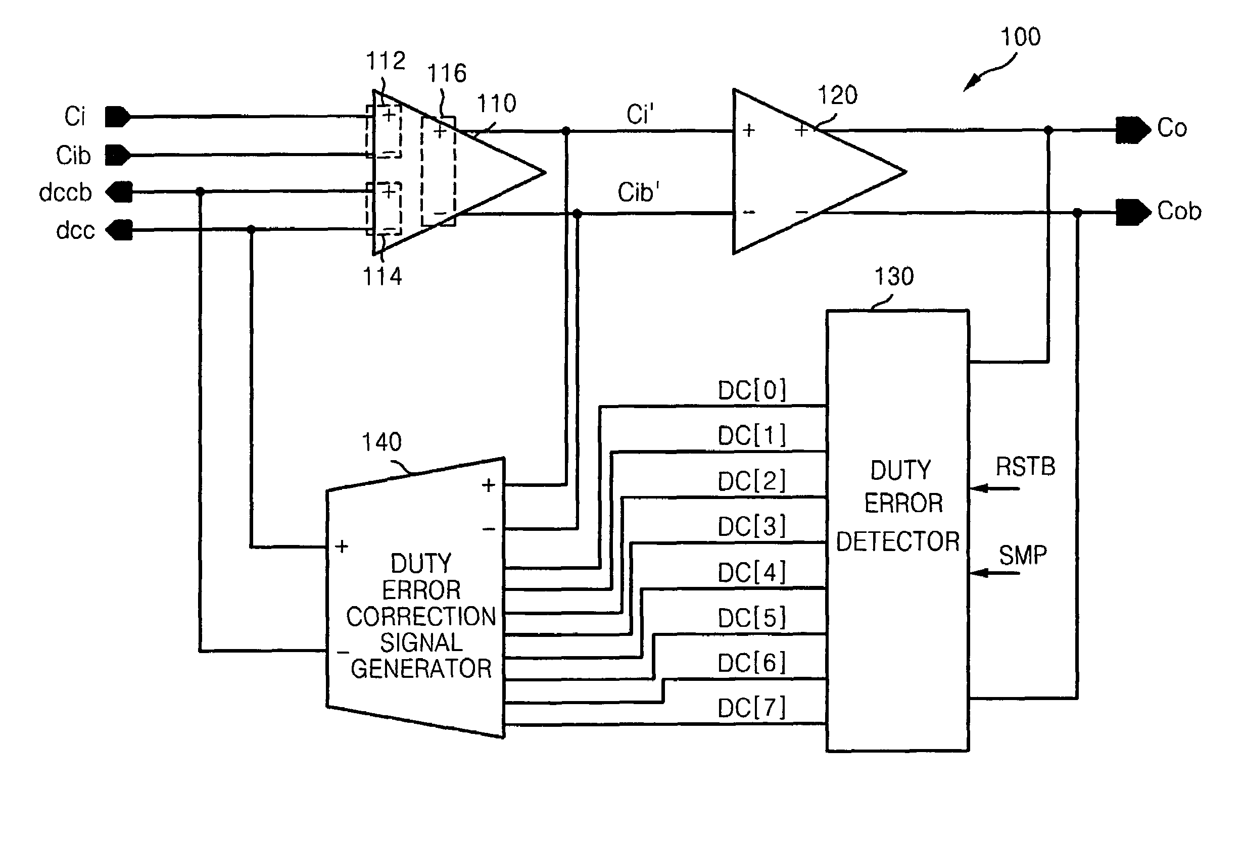
[0035]FIG. 3 illlustrates a block diagram of a duty cycle correction circuit according to an example embodiment of the present invention. Referring to FIG. 3, the duty cycle correction circuit 100 may in...


PUM


Abstract

A duty cycle correction circuit may include an error corrector adapted to correct duty cycles of first differential analog clock signals input to a pair of input terminals based on duty cycle correction signals input to a pair of control terminals and to output second differential analog clock signals having corrected duty cycles through a pair of output terminals, an analog to digital buffer adapted to convert the second differential analog clock signals to differential digital clock signals, a duty error detector adapted to detect duty cycles of the differential digital clock signals and to output a N bit digital signal, and a duty error correction signal generator adapted to output differential control current signals having current gains controlled based on the second differential analog clock signals and the N bit digital signal to the pair of control terminals as the duty cycle correction signals.

Description

BACKGROUND OF THE INVENTION[0001]1. Field of the Invention[0002]Embodiments of the present invention relate to a duty cycle correction circuit, and more particularly, to a duty cycle correction circuit adjusting current characteristic using a digital duty error detector and a method thereof.[0003]2. Description of the Related Art[0004]For systems that use a multi-phase clock signal, e.g., Double Data Rate Synchronous Dynamic Random Access Memory (DDR SDRAM), an analog to digital converter (ADC), etc., an analog duty cycle correction circuit may be used to maintain a constant, e.g., 50%, duty cycle (or duty rate).[0005]Since the analog duty cycle correction circuit stores information on duty error, e.g., deviation from a desired duty cycle, in a capacitor, information on the duty error may be damaged by a leakage current of the capacitor when the analog duty cycle correction circuit is powered off in a power down mode to reduce power consumption. When the analog duty cycle correction...

Claims


Application Information

Patent Timeline
Patent Type & Authority Patents(United States)
IPC IPC(8): H03K3/017
CPCH03K5/1565H03K5/133G11C11/40G11C29/00
Inventor CHOI, HYUN SUKIM, CHAN KYUNG
Owner SAMSUNG ELECTRONICS CO LTD
Learn More