
Optical sight having obscured reticle illumination

a technology of optical sight and illumination, applied in the field of optical sight having obscured reticle illumination, to achieve the effect of little to the cost of optical sigh

Active Publication Date: 2009-03-10
RAYTHEON CANADA LTD
View PDF15 Cites 6 Cited by
  • Summary
  • Abstract
  • Description
  • Claims
  • Application Information

AI Technical Summary

Benefits of technology

[0009]The present invention prevents such light leakage from the reticle and its illumination. The present approach does not interfere with or alter the operation of the optical sight and its illuminated reticle, does not adversely affect the performance of the reticle, and does not consume energy.
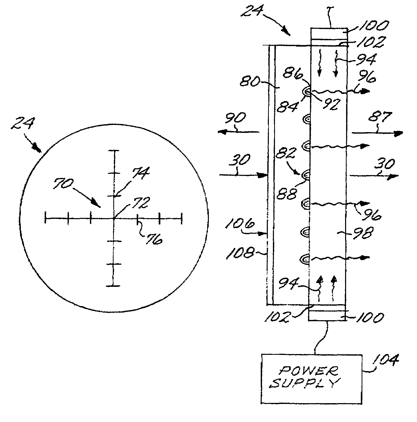
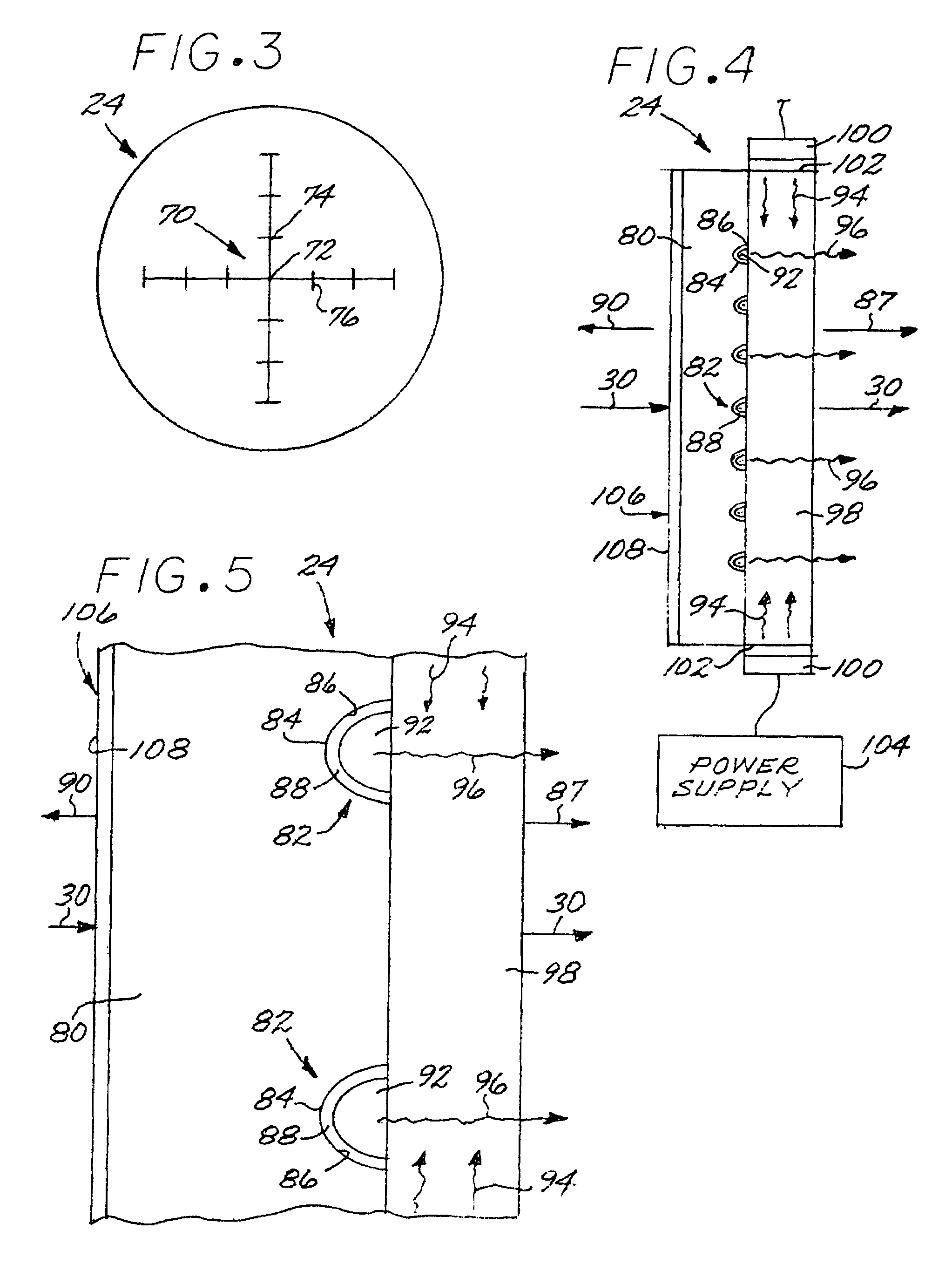
[0015]The present approach provides a controllably illuminated reticle pattern that is visible to the user of the optical sight under a wide variety of daylight, semi-darkness, and darkness conditions. The reticle pattern and its excitation energy are not, however, visible to someone trying to detect the presence of the user of the optical sight either with the unaided eye or using a detector, inasmuch as emissions from the input end of the optical sight are obscured by techniques that do not in turn block the visibility of the target to the user of the optical sight. The present approach adds little to the cost of the optical sight, while providing these significant benefits.

Problems solved by technology

One cause of potential concern is that exterior light may reflect from the lenses of the optical sight to reveal the presence of the optical sight.

Method used


Image

  • Optical sight having obscured reticle illumination
  • Optical sight having obscured reticle illumination
  • Optical sight having obscured reticle illumination

Examples


Embodiment Construction

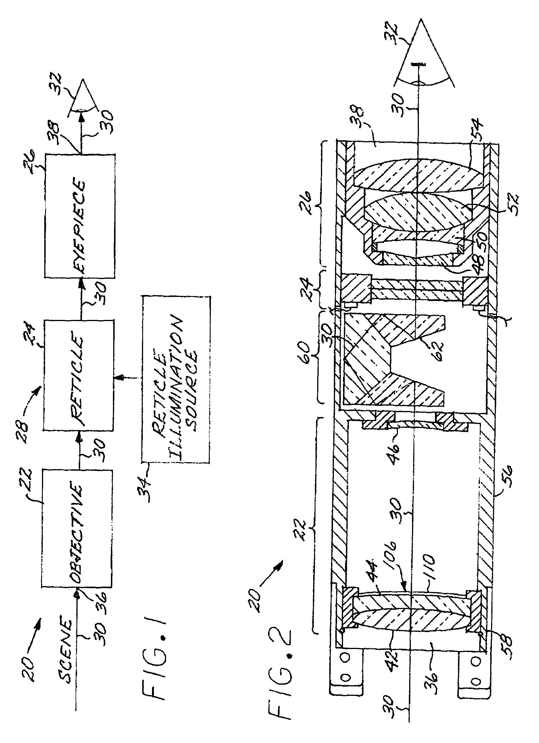
[0022]FIG. 1 depicts in general form an optical sight 20 according to the present approach. The optical sight 20 comprises optical elements including an objective 22, a reticle 24, and an eyepiece 26. Each of the objective 22 and the eyepiece 26 preferably includes one or more optically powered lenses. The objective 22, the reticle 24, and the eyepiece 26 together constitute an optical train 28 with an optical path 30 therethrough shown as a vector. Light travels along the optical path 30 from a scene to an input end 36 at of the optical train 28 at the objective 22, from the objective 22 to the eyepiece 26, from the eyepiece 26 to an output end 38 of the optical train 28, and thence to an eye 32 of the user of the optical sight. The input end 36 is at the front of the objective 22 nearest the scene, and the output end 38 is at the back of the eyepiece 26 nearest the eye 32 of the user. The reticle 24 is superimposed upon and coincident with the optical path 30 at some point before ...


PUM


Abstract

An optical sight includes an optical train with a reticle having a reticle substrate, and a reticle relief pattern in the reticle substrate having a relief surface oriented so that the relief surface faces an output end of the optical sight. A layer of a barrier material that is opaque to visible light is deposited upon the relief surface. There is a wavelength-converting material within the reticle relief pattern that converts a non-visible excitation wavelength to visible light. A light source of the non-visible excitation wavelength controllably illuminates the wavelength-converting material. The optical train prevents the non-visible wavelength from propagating out of the input end of the optical train.

Description

[0001]This invention relates to an optical sight having a reticle and, more particularly, to such an optical sight constructed to prevent its detection as a result of radiated energy.BACKGROUND OF THE INVENTION[0002]Refractive or reflective optical sights are used in a wide variety of applications to obtain increased magnification of a scene. In one common application, an optical sight is affixed to the upper side of the barrel of a rifle-type weapon used by a soldier. The user sights through the optical sight to acquire a target and aim the weapon toward the target to increase the likelihood of hitting the target with a projectile fired from the weapon.[0003]A reticle is typically provided in the optical path of the optical sight. The reticle normally has reference markings or other information that aids the user in aiming the optical sight and thence the weapon toward the intended target. The reference markings usually include a cross hair or similar marking to indicate the bore s...

Claims


Application Information

Patent Timeline
Patent Type & Authority Patents(United States)
IPC IPC(8): G02B23/00
CPCF41G1/345F41G1/38G02B17/045G02B23/14G02B27/34
Inventor STENTON, CONRAD
Owner RAYTHEON CANADA LTD
Learn More