Techniques for modifying image field data as a function of radius across the image field

a technology of image field and radius, applied in the field of video signal processing, can solve the problems of significantly non-uniform image of scene, which is not suitable for most optical applications, and achieves the effect of low cost and not adversely affecting the performance of the video system

Inactive Publication Date: 2008-11-06
QUALCOMM INC
View PDF29 Cites 3 Cited by
  • Summary
  • Abstract
  • Description
  • Claims
  • Application Information

AI Technical Summary

Benefits of technology

[0006]The electronic signal processing techniques of the present invention allow compensation for lens shading and / or other similar phenomenon, such as sensor sensitivity variations and internal camera reflections, which superimpose a predictable optical variation onto the image across the multi-element sensor. These techniques have particular application to digital cameras and other types of video devices but are not limited to such applications. The techniques may be implemented at a low cost, take practically none of the valuable space in portable devices and operate at the same rate as the video data being modified is obtained from the photo-sensor, thereby not adversely affecting the performance of the video system.
[0007]In an example of lens shading compensation, a spherical intensity correction to the video data is made by correcting the data of each image pixel by an amount that is a function of the radius of the pixel from the optical center of the image. The position of each pixel is first converted from a x-y coordinate position of the raster or other linear scanning pattern to a radial distance, and then that radial distance is used to generate the correction for the pixel from a small amount of correction information. This avoids having to keep correction data for each pixel, and thus saves having to include a large memory to store such data. Use of circuits dedicated to carrying out these operations allows them to be performed at the same rate as the video data is outputted by the photosensor, without having to employ an extremely fast, expensive digital signal processor. In a particular application, the radial position of a pixel is calculated from the scan position by an adder circuit.

Problems solved by technology

That is, a simple lens used to view a scene with a uniform light intensity across it will typically produce an image of that scene having a significantly non-uniform light intensity.
Such a lens obviously is not suitable for most optical applications without this effect being corrected.

Method used


Image

  • Techniques for modifying image field data as a function of radius across the image field
  • Techniques for modifying image field data as a function of radius across the image field
  • Techniques for modifying image field data as a function of radius across the image field

Examples


Embodiment Construction

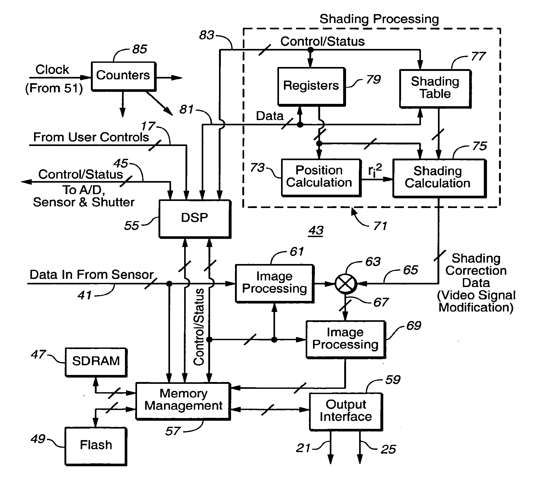
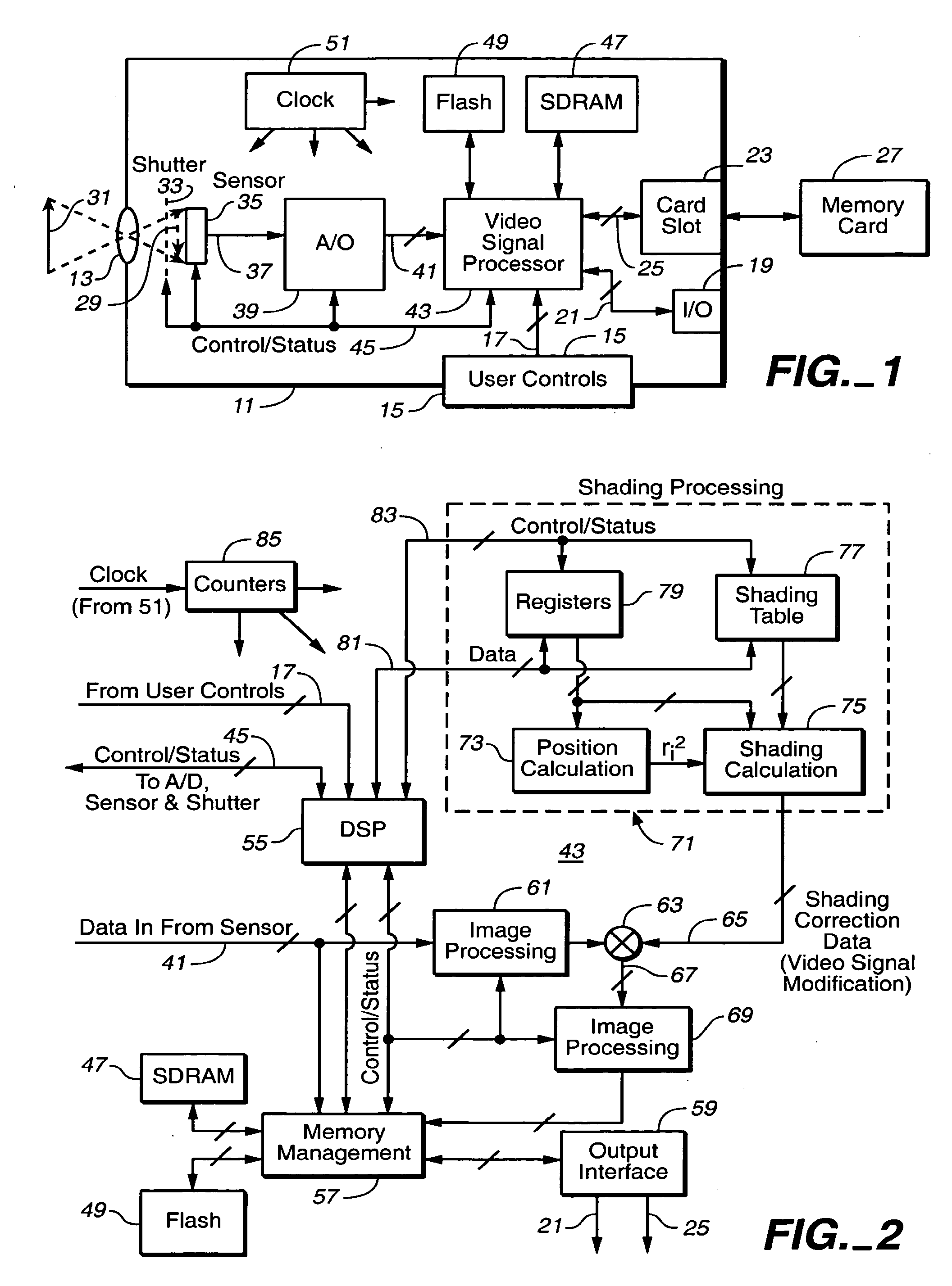
[0018]An implementation of the techniques of the present invention is described in a camera or other video acquisition device where digital data of the image(s) are modified on the fly to compensate for intensity modifications superimposed across the image by the camera's optical system, photo-sensor and reflections from internal camera surfaces. In FIG. 1, such a camera is schematically shown to include a case 11, an imaging optical system 13, user controls 15 that generate control signals 17, a video input-output receptacle 19 with internal electrical connections 21, and a card slot 23, with internal electrical connections 25, into which a non-volatile memory card 27 is removably inserted. Data of images captured by the camera may be stored on the memory card 27 or on an internal non-volatile memory (not shown). Image data may also be outputted to another video device through the receptacle 19. The memory card 27 can be a commercially available semiconductor flash electrically era...


PUM


Abstract

A technique for modifying data of an image, such as can be implemented in a still camera or video recorder in order to correct for defects in its optical and / or electronic systems, includes generating data to modify the image as a function of radial position across it. A variation of the intensity across an image (lens shading) that appears in data from a two-dimensional detector is an example of an application of the technique. In order to make modifications to the data, positions of a two-dimensional raster scan pattern of an image sensor are converted to radial positions and this is then used to generate the modification data. The modification data is generated on the fly, at the same rate as the image data is being acquired, so that the modification takes place without slowing down data transfer from the image sensor.

Description

CROSS-REFERENCE TO RELATED APPLICATIONS[0001]This utility patent application is a Continuation of allowed U.S. patent application Ser. No. 10 / 222,412 filed on Aug. 16, 2002, the benefit of which is claimed under 35 U.S.C. §120, and is further incorporated herein by reference.FIELD OF THE INVENTION[0002]This invention relates generally to techniques of processing video signal data, and, more specifically, to processing video binary data to correct for variations across an imaged optical field such as, for example, to compensate for shading effects caused by lenses, sensor sensitivity variations and housing internal reflections in cameras and the like.BACKGROUND OF THE INVENTION[0003]Lens shading is a phenomenon of a non-uniform light response across an image field of a lens. That is, a simple lens used to view a scene with a uniform light intensity across it will typically produce an image of that scene having a significantly non-uniform light intensity. The light intensity is normal...

Claims


Application Information

Patent Timeline
Patent Type & Authority Applications(United States)
IPC IPC(8): H04N9/64G06K9/40H04N5/225H04N1/401H04N5/243H04N101/00
CPCH04N5/217H04N5/2178H04N5/243H04N25/67H04N23/81H04N23/76
Inventor PINTO, VICTORGALIL, EREZ
Owner QUALCOMM INC
Why Eureka
Try Eureka