Means for covering the flange of a waste water strainer

a waste water strainer and flange technology, which is applied in the direction of hose connections, washstands, mechanical equipment, etc., can solve the problems of insufficient use of conventional tools for strainer removal, incompatibility of replacement strainer threads with fittings or bushings, and often difficult task of strainer removal

Active Publication Date: 2009-03-17
WCM IND INC
View PDF9 Cites 84 Cited by
  • Summary
  • Abstract
  • Description
  • Claims
  • Application Information

AI Technical Summary

Problems solved by technology

Occasionally it is necessary to change the strainer of a given receptacle because the flange thereof has become tarnished, disfigured, or because the flange is incompatible esthetically with the owner's sense of ornamentation.
Removal of the strainer is often a difficult task, particularly when the strainer has been in place for a long time.
Conventional tools are typically insufficient for use in removal of the strainer.
Further, there is a possibility that the threads of the replacement strainer will not be compatible with the threads of the fitting or bushing associated with the aperture of the receptacle.
In addition, when the strainer is removed there is nothing to retain the back drain system and it falls away.
This approach to the installation of a substitute flange is not satisfactory because variations of thread sizes in the original strainers are often incompatible with the thread sizes of the substituted flange adapter.

Method used


Image

  • Means for covering the flange of a waste water strainer
  • Means for covering the flange of a waste water strainer
  • Means for covering the flange of a waste water strainer

Examples


Embodiment Construction

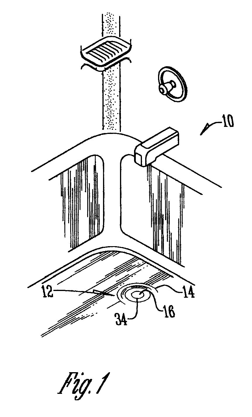
[0014]The numeral 10 designates a fluid compartment or receptacle such as a tub or a sink. Compartment 10 has a bottom 12 with an interior bottom surface 14. A waste water aperture 16 is located in bottom 12.

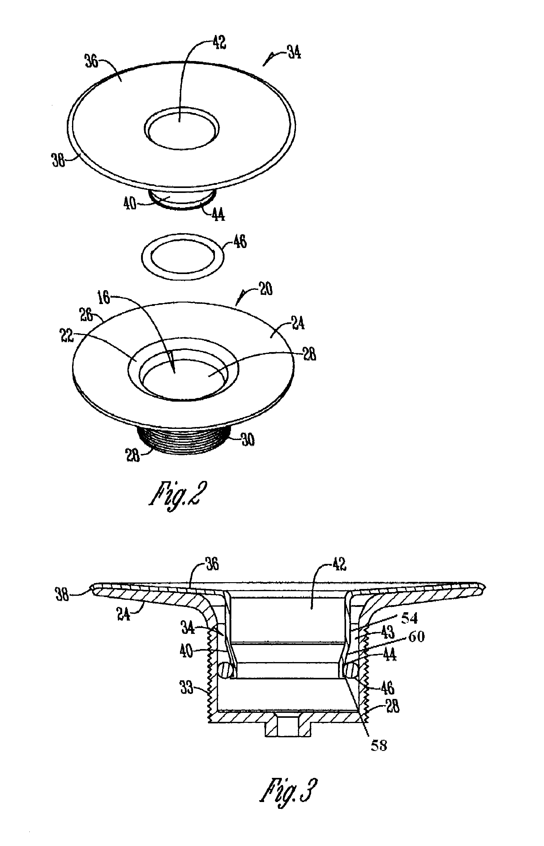
[0015]A waste water strainer 20 is shown in FIG. 2. Strainer 20 has an upper end 22 from which a circular flange 24 extends. The outer perimeter 26 of flange 24 engages the interior bottom surface 14 (FIG. 1) surrounding aperture 16. The strainer 20 has a downwardly extending cylindrical wall 28 and external threads 30. The typical closure valves which may be associated with strainer 20 have not been shown.

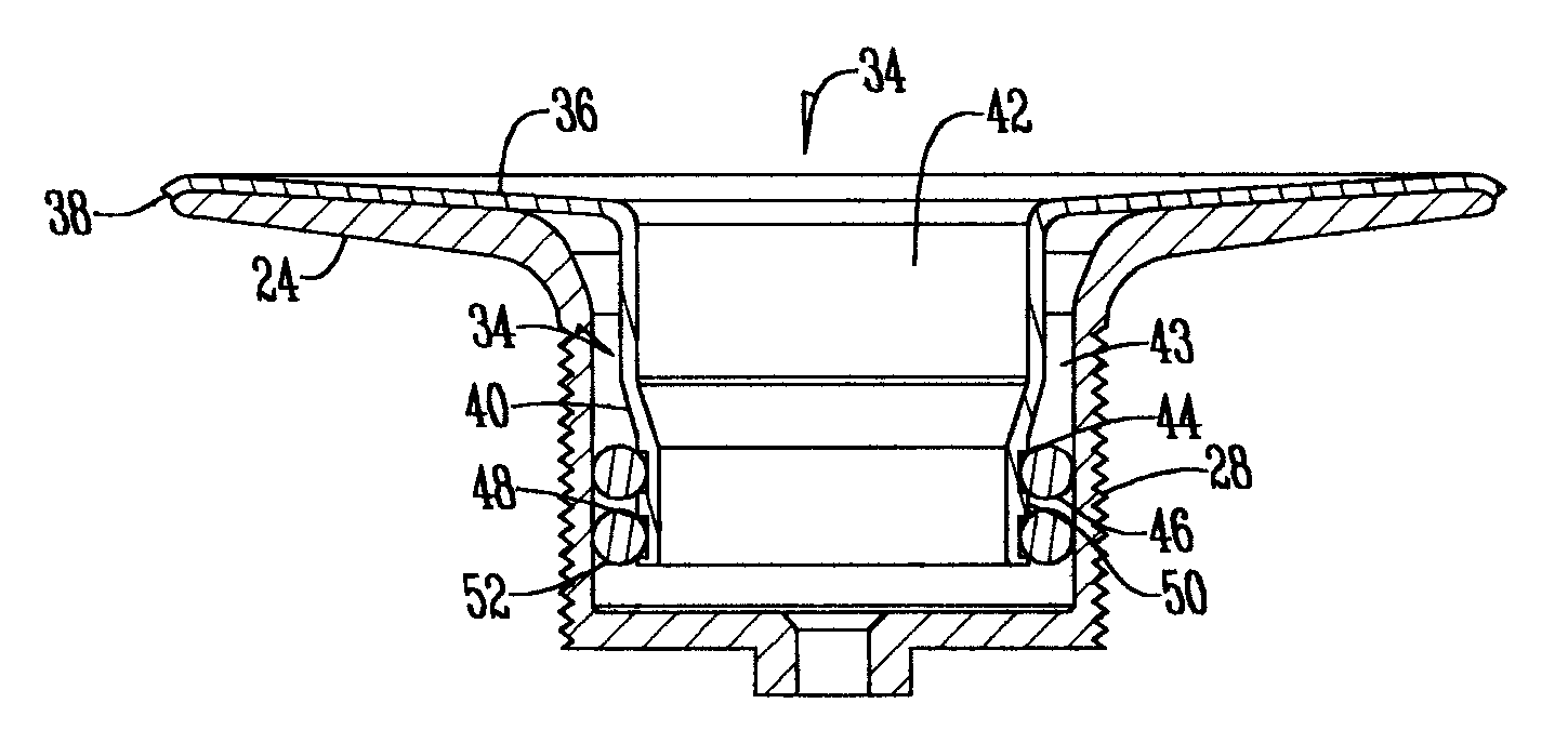
[0016]The numeral 34 designates a waste water insert. Insert 34 has a flange 36 with the periphery thereof terminating in a downwardly extending lip 38. As best shown in FIG. 3, the lip 38 extends downwardly and over the outer perimeter 26 of flange 24 of strainer 20. The lip 38 engages the bottom 12 of compartment 10 when installed.

[0017]Insert 34 has a downwardly extending w...


PUM


Abstract

A waste water insert has a cylindrical wall surrounding a vertical cylindrical bore. A horizontal flange extends outwardly from the upper end of the wall and has a lip formed on its outer periphery. The horizontal flange of the waste water insert is super-imposed over the horizontal flange of a waste water strainer located in a bathtub, sink or the like. The cylindrical wall of the insert extends downwardly through the cylindrical wall of the waste water strainer with the two walls being spaced from each other by virtue of the cylindrical wall of the insert having a smaller diameter than that of the strainer. One or more grooves are within the cylindrical wall of the insert and receive resilient rings that engage the cylindrical wall of the strainer.

Description

BACKGROUND OF THE INVENTION[0001]A strainer in the plumbing field is the mechanism in the bottom of a sink, bathtub, or the like through which waste water flows from the receptacle. Strainers usually have valves or the like which control the flow of water therethrough. Most of these valve assemblies are threadably mounted within a threaded aperture located in the strainer.[0002]Existing strainers have a vertically disposed externally threaded sleeve which engage corresponding threads on a fitting adjacent a vertically disposed aperture in the bottom of the water receptacle. The upper end of the sleeve terminates in a circular horizontal flange which engages and is sealed to the bottom of the receptacle around the aperture in the bottom of the receptacle. A hub with a threaded bore and with radially extending spokes is often located in a horizontal plane in the bottom of the strainer to support various closure valves.[0003]Occasionally it is necessary to change the strainer of a give...

Claims


Application Information

Patent Timeline
Patent Type & Authority Patents(United States)
IPC IPC(8): A47K1/14
CPCE03C1/22
Inventor BALL, WILLIAM T.
Owner WCM IND INC
Why Eureka
Try Eureka